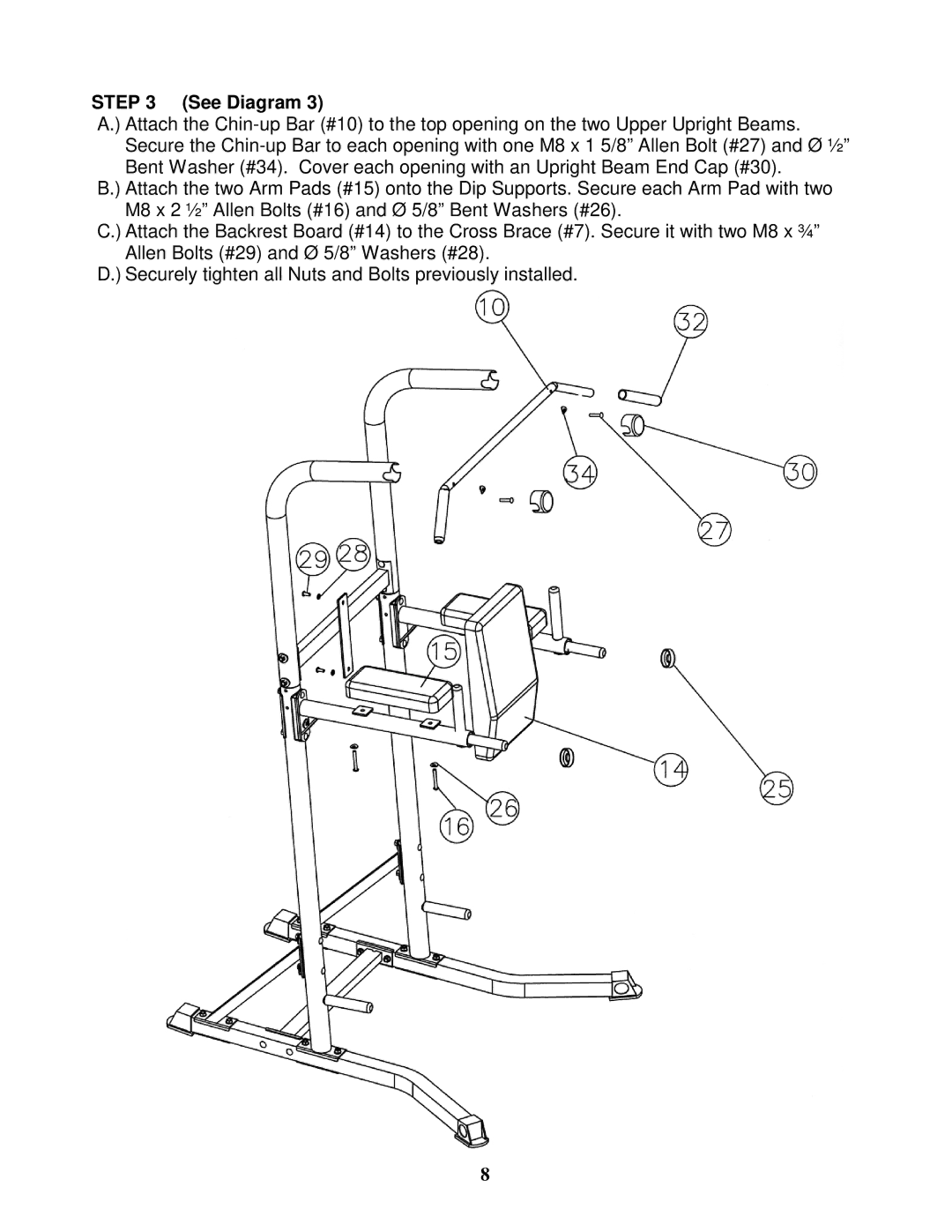
STEP 3 (See Diagram 3)
A.) Attach the
B.) Attach the two Arm Pads (#15) onto the Dip Supports. Secure each Arm Pad with two M8 x 2 ½” Allen Bolts (#16) and Ø 5/8” Bent Washers (#26).
C.) Attach the Backrest Board (#14) to the Cross Brace (#7). Secure it with two M8 x ¾” Allen Bolts (#29) and Ø 5/8” Washers (#28).
D.) Securely tighten all Nuts and Bolts previously installed.
8