ASSEMBLY INSTRUCTION
Tools Required Assembling the Machine: Two Adjustable Wrenches and Allen
Wrenches. NOTE: It is strongly recommended two or more people assembling this machine to avoid possible injury.
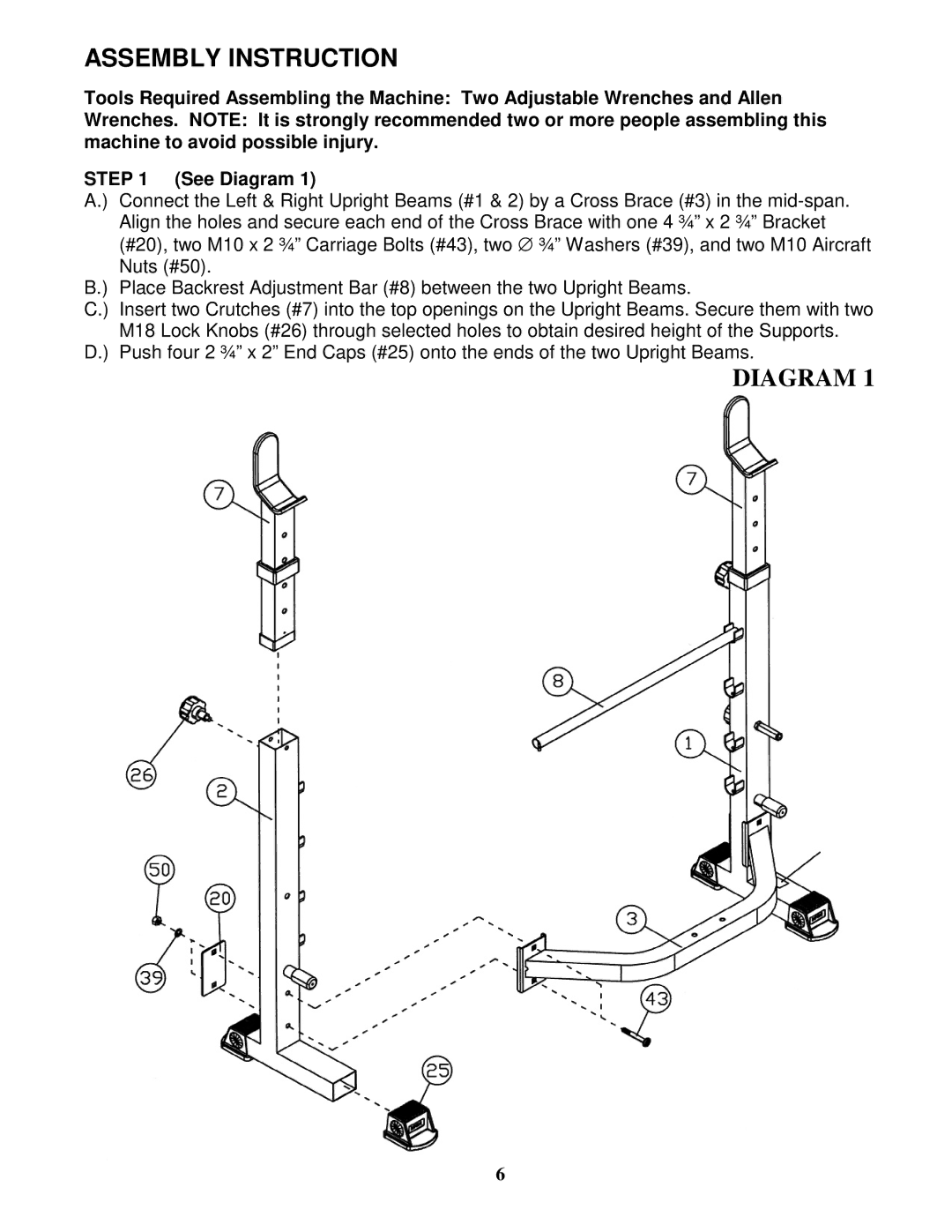
STEP 1 (See Diagram 1)
A.) | Connect the Left & Right Upright Beams (#1 & 2) by a Cross Brace (#3) in the |
| Align the holes and secure each end of the Cross Brace with one 4 ¾” x 2 ¾” Bracket |
| (#20), two M10 x 2 ¾” Carriage Bolts (#43), two ∅ ¾” Washers (#39), and two M10 Aircraft |
| Nuts (#50). |
B.) | Place Backrest Adjustment Bar (#8) between the two Upright Beams. |
C.) | Insert two Crutches (#7) into the top openings on the Upright Beams. Secure them with two |
M18 Lock Knobs (#26) through selected holes to obtain desired height of the Supports. D.) Push four 2 ¾” x 2” End Caps (#25) onto the ends of the two Upright Beams.
DIAGRAM 1
6