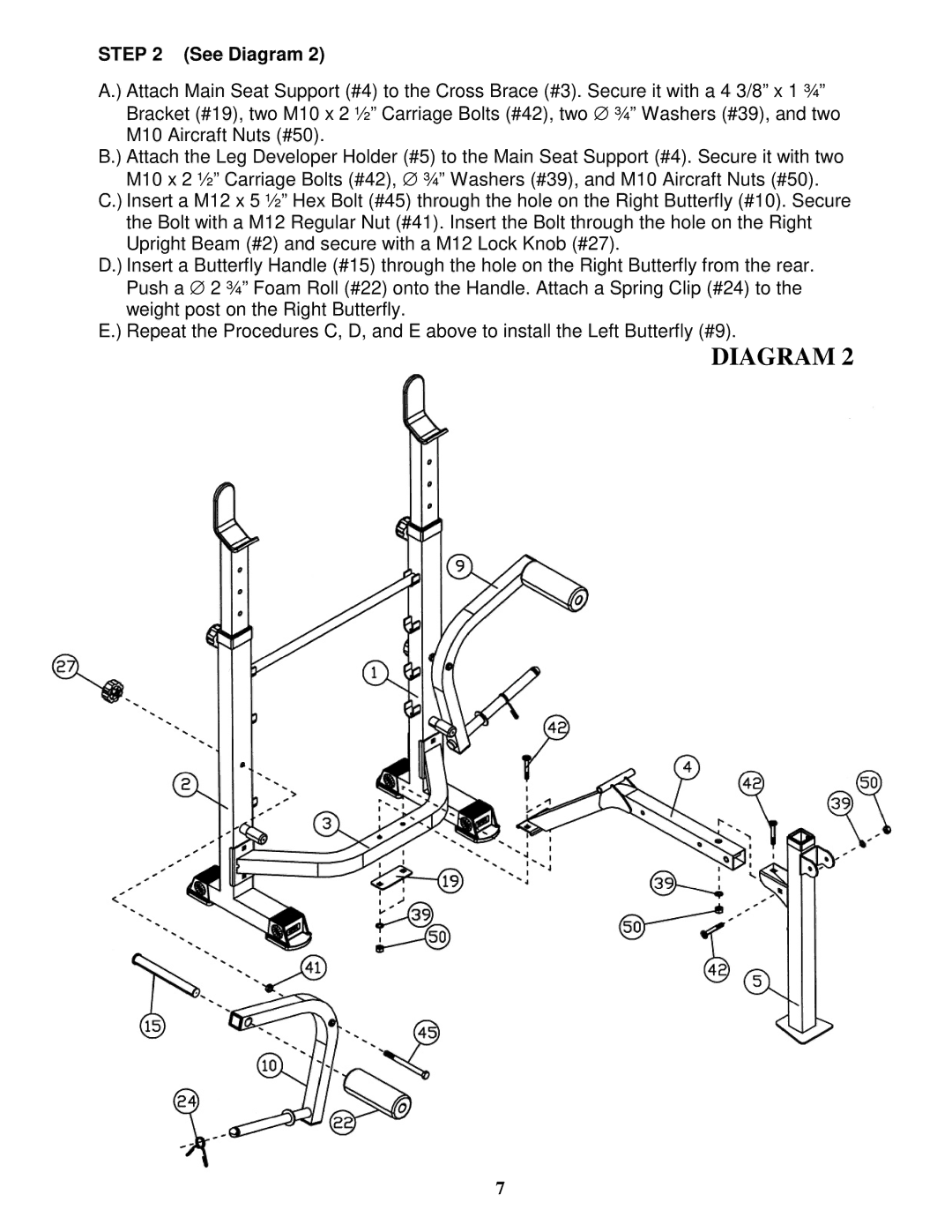
STEP 2 (See Diagram 2)
A.) Attach Main Seat Support (#4) to the Cross Brace (#3). Secure it with a 4 3/8” x 1 ¾” Bracket (#19), two M10 x 2 ½” Carriage Bolts (#42), two ∅ ¾” Washers (#39), and two M10 Aircraft Nuts (#50).
B.) Attach the Leg Developer Holder (#5) to the Main Seat Support (#4). Secure it with two M10 x 2 ½” Carriage Bolts (#42), ∅ ¾” Washers (#39), and M10 Aircraft Nuts (#50).
C.) Insert a M12 x 5 ½” Hex Bolt (#45) through the hole on the Right Butterfly (#10). Secure the Bolt with a M12 Regular Nut (#41). Insert the Bolt through the hole on the Right Upright Beam (#2) and secure with a M12 Lock Knob (#27).
D.) Insert a Butterfly Handle (#15) through the hole on the Right Butterfly from the rear. Push a ∅ 2 ¾” Foam Roll (#22) onto the Handle. Attach a Spring Clip (#24) to the weight post on the Right Butterfly.
E.) Repeat the Procedures C, D, and E above to install the Left Butterfly (#9).
DIAGRAM 2
7
