ASSEMBLY INSTRUCTION
Tools Required Assembling the Machine: Two Adjustable Wrenches and Allen
Wrenches. NOTE: It is strongly recommended two or more people assembling this machine to avoid possible injury.
STEP 1 (See Exploded Diagram)
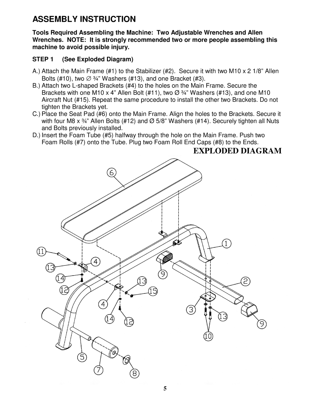
A.) Attach the Main Frame (#1) to the Stabilizer (#2). Secure it with two M10 x 2 1/8” Allen Bolts (#10), two ∅ ¾” Washers (#13), and one Bracket (#3).
B.) Attach two
C.) Place the Seat Pad (#6) onto the Main Frame. Align the holes to the Brackets. Secure it with four M8 x ¾” Allen Bolts (#12) and Ø 5/8” Washers (#14). Securely tighten all Nuts and Bolts previously installed.
D.) Insert the Foam Tube (#5) halfway through the hole on the Main Frame. Push two Foam Rolls (#7) onto the Tube. Plug two Foam Roll End Caps (#8) to the Ends.
EXPLODED DIAGRAM
5