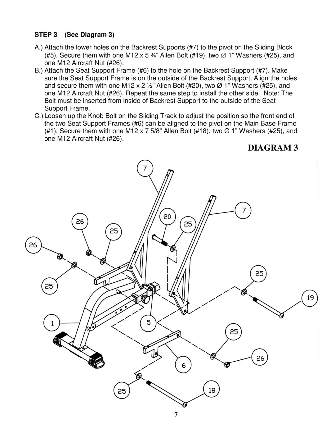
STEP 3 (See Diagram 3)
A.) Attach the lower holes on the Backrest Supports (#7) to the pivot on the Sliding Block (#5). Secure them with one M12 x 5 ¾” Allen Bolt (#19), two ∅ 1” Washers (#25), and one M12 Aircraft Nut (#26).
B.) Attach the Seat Support Frame (#6) to the hole on the Backrest Support (#7). Make sure the Seat Support Frame is on the outside of the Backrest Support. Align the holes and secure them with one M12 x 2 ½” Allen Bolt (#20), two Ø 1” Washers (#25), and one M12 Aircraft Nut (#26). Repeat the same step to install the other side. Note: The Bolt must be inserted from inside of Backrest Support to the outside of the Seat Support Frame.
C.) Loosen up the Knob Bolt on the Sliding Track to adjust the position so the front end of the two Seat Support Frames (#6) can be aligned to the pivot on the Main Base Frame (#1). Secure them with one M12 x 7 5/8” Allen Bolt (#18), two Ø 1” Washers (#25), and one M12 Aircraft Nut (#26).
DIAGRAM 3
7