5
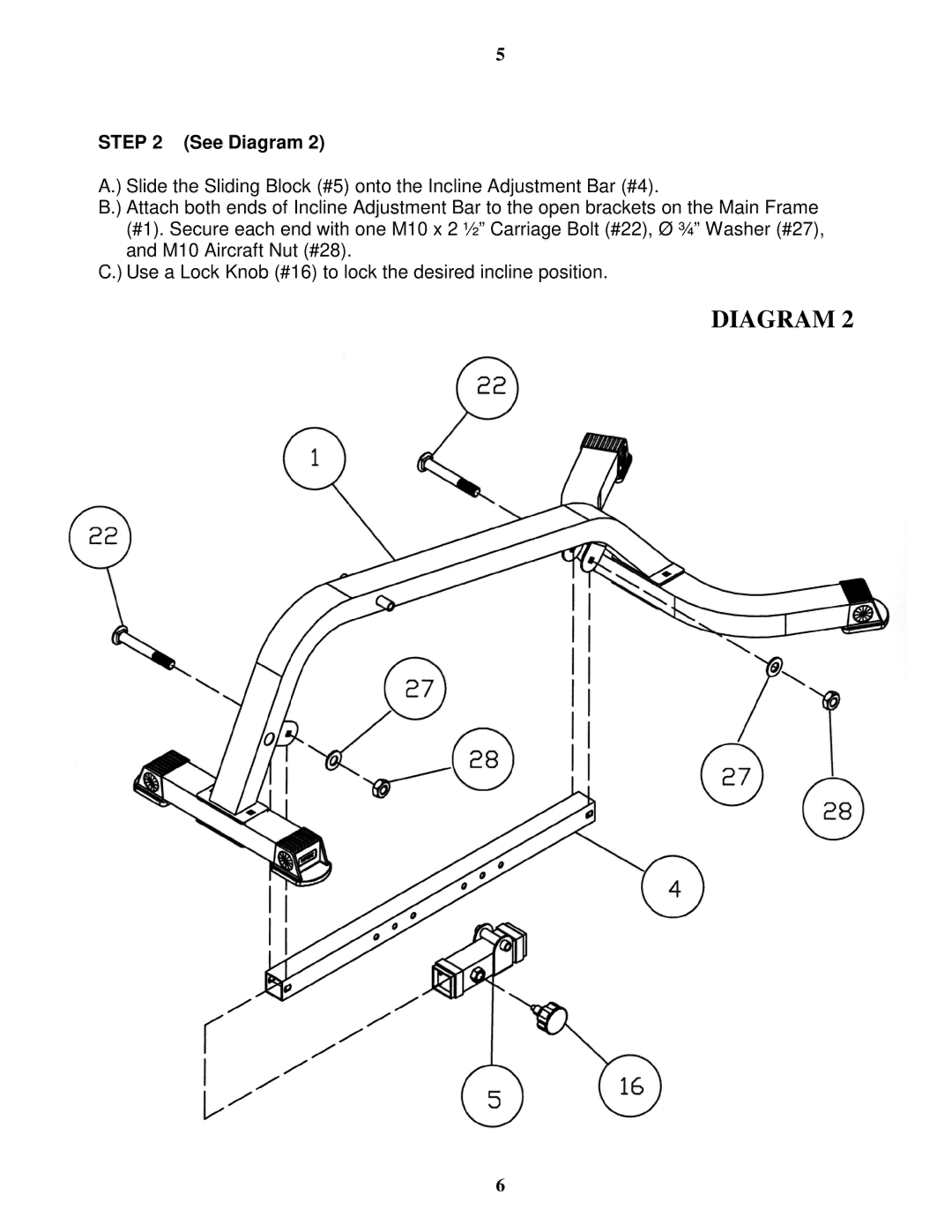
STEP 2 (See Diagram 2)
A.) Slide the Sliding Block (#5) onto the Incline Adjustment Bar (#4).
B.) Attach both ends of Incline Adjustment Bar to the open brackets on the Main Frame (#1). Secure each end with one M10 x 2 ½” Carriage Bolt (#22), Ø ¾” Washer (#27), and M10 Aircraft Nut (#28).
C.) Use a Lock Knob (#16) to lock the desired incline position.
DIAGRAM 2
6