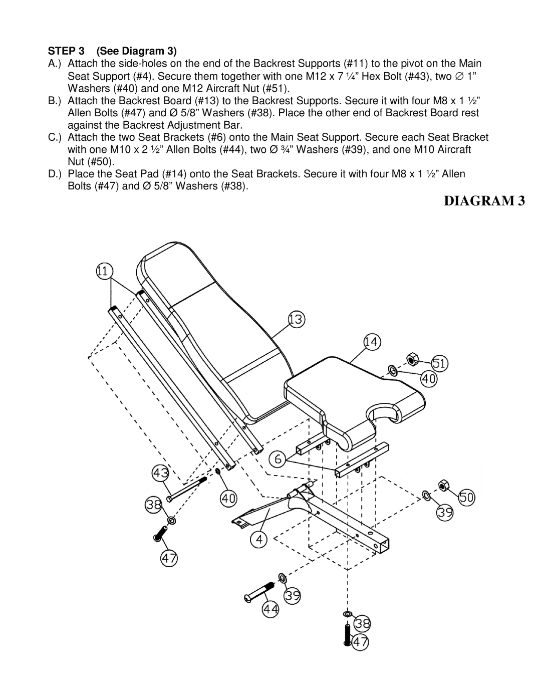
STEP 3 (See Diagram 3)
A.) Attach the
B.) Attach the Backrest Board (#13) to the Backrest Supports. Secure it with four M8 x 1 ½” Allen Bolts (#47) and Ø 5/8” Washers (#38). Place the other end of Backrest Board rest against the Backrest Adjustment Bar.
C.) Attach the two Seat Brackets (#6) onto the Main Seat Support. Secure each Seat Bracket with one M10 x 2 ½” Allen Bolts (#44), two Ø ¾” Washers (#39), and one M10 Aircraft Nut (#50).
D.) Place the Seat Pad (#14) onto the Seat Brackets. Secure it with four M8 x 1 ½” Allen Bolts (#47) and Ø 5/8” Washers (#38).