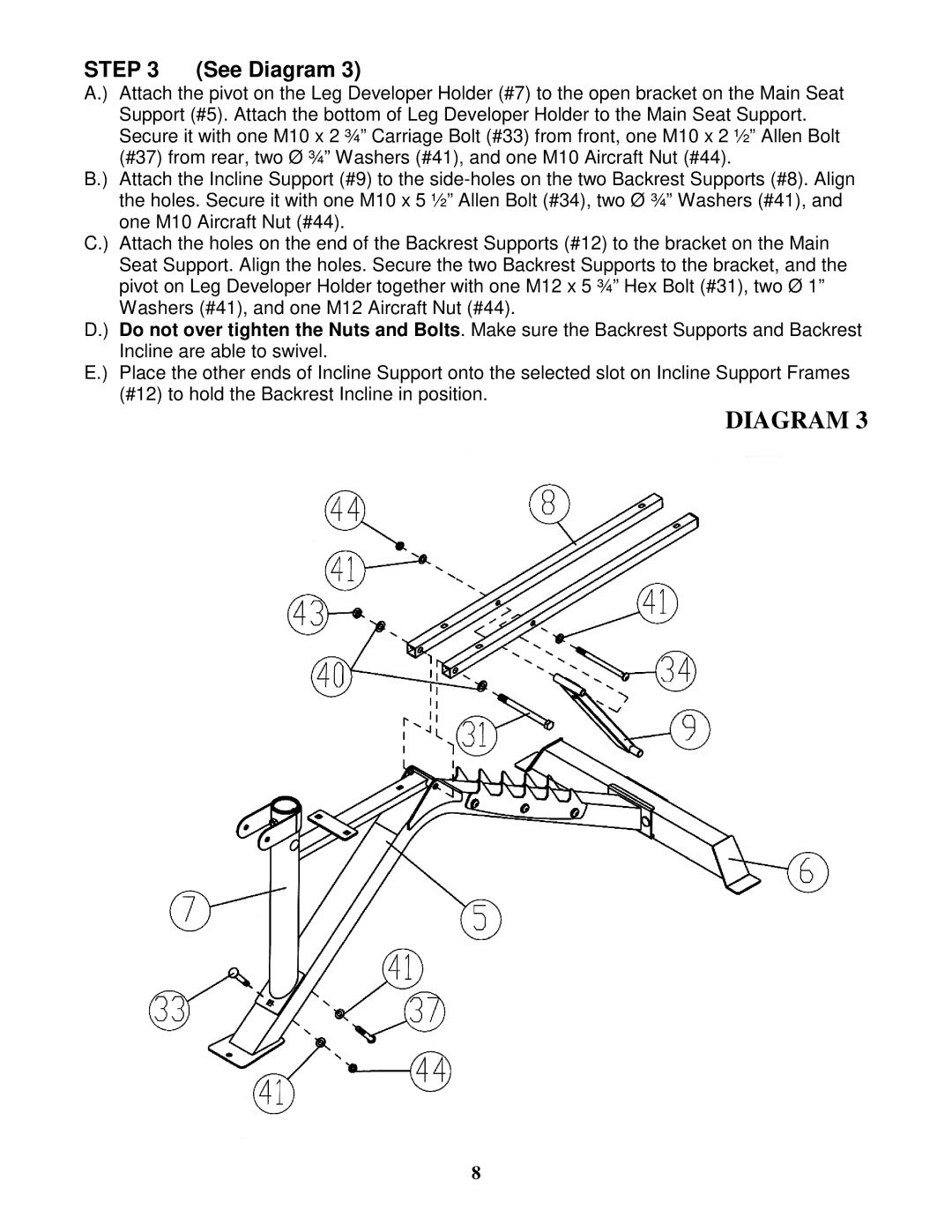
STEP 3 (See Diagram 3)
A.) Attach the pivot on the Leg Developer Holder (#7) to the open bracket on the Main Seat Support (#5). Attach the bottom of Leg Developer Holder to the Main Seat Support. Secure it with one M10 x 2 ¾” Carriage Bolt (#33) from front, one M10 x 2 ½” Allen Bolt (#37) from rear, two Ø ¾” Washers (#41), and one M10 Aircraft Nut (#44).
B.) Attach the Incline Support (#9) to the
C.) Attach the holes on the end of the Backrest Supports (#12) to the bracket on the Main Seat Support. Align the holes. Secure the two Backrest Supports to the bracket, and the pivot on Leg Developer Holder together with one M12 x 5 ¾” Hex Bolt (#31), two Ø 1” Washers (#41), and one M12 Aircraft Nut (#44).
D.) Do not over tighten the Nuts and Bolts. Make sure the Backrest Supports and Backrest Incline are able to swivel.
E.) Place the other ends of Incline Support onto the selected slot on Incline Support Frames (#12) to hold the Backrest Incline in position.
DIAGRAM 3
8