ASSEMBLY INSTRUCTION
Tools Required Assembling the Machine: Two Adjustable Wrenches and Allen Wrenches.
NOTE: It is strongly recommended two or people assembling this machine to avoid possible injury.
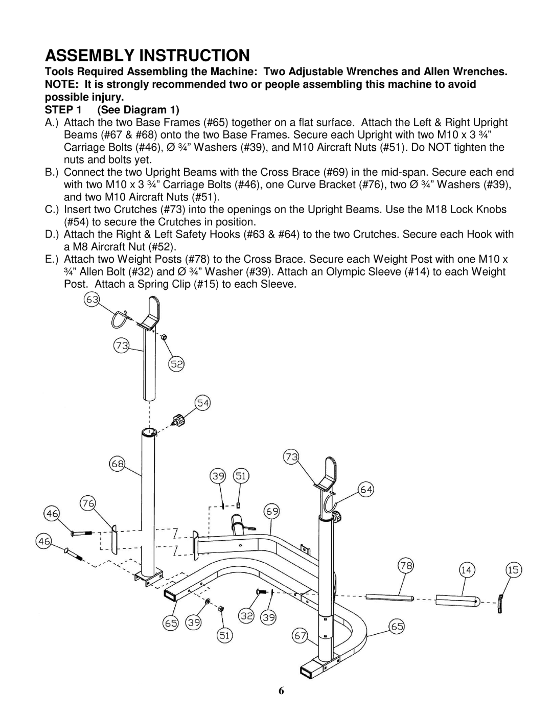
STEP 1 (See Diagram 1)
A.) Attach the two Base Frames (#65) together on a flat surface. Attach the Left & Right Upright Beams (#67 & #68) onto the two Base Frames. Secure each Upright with two M10 x 3 ¾” Carriage Bolts (#46), Ø ¾” Washers (#39), and M10 Aircraft Nuts (#51). Do NOT tighten the nuts and bolts yet.
B.) Connect the two Upright Beams with the Cross Brace (#69) in the
C.) Insert two Crutches (#73) into the openings on the Upright Beams. Use the M18 Lock Knobs (#54) to secure the Crutches in position.
D.) Attach the Right & Left Safety Hooks (#63 & #64) to the two Crutches. Secure each Hook with a M8 Aircraft Nut (#52).
E.) Attach two Weight Posts (#78) to the Cross Brace. Secure each Weight Post with one M10 x ¾” Allen Bolt (#32) and Ø ¾” Washer (#39). Attach an Olympic Sleeve (#14) to each Weight Post. Attach a Spring Clip (#15) to each Sleeve.
6
