ASSEMBLY INSTRUCTION
Tools required for assembling the Machine: Two Adjustable Wrenches and Allen Wrenches.
NOTE: It is strongly recommended that two or more people assemble this machine to avoid possible injury.
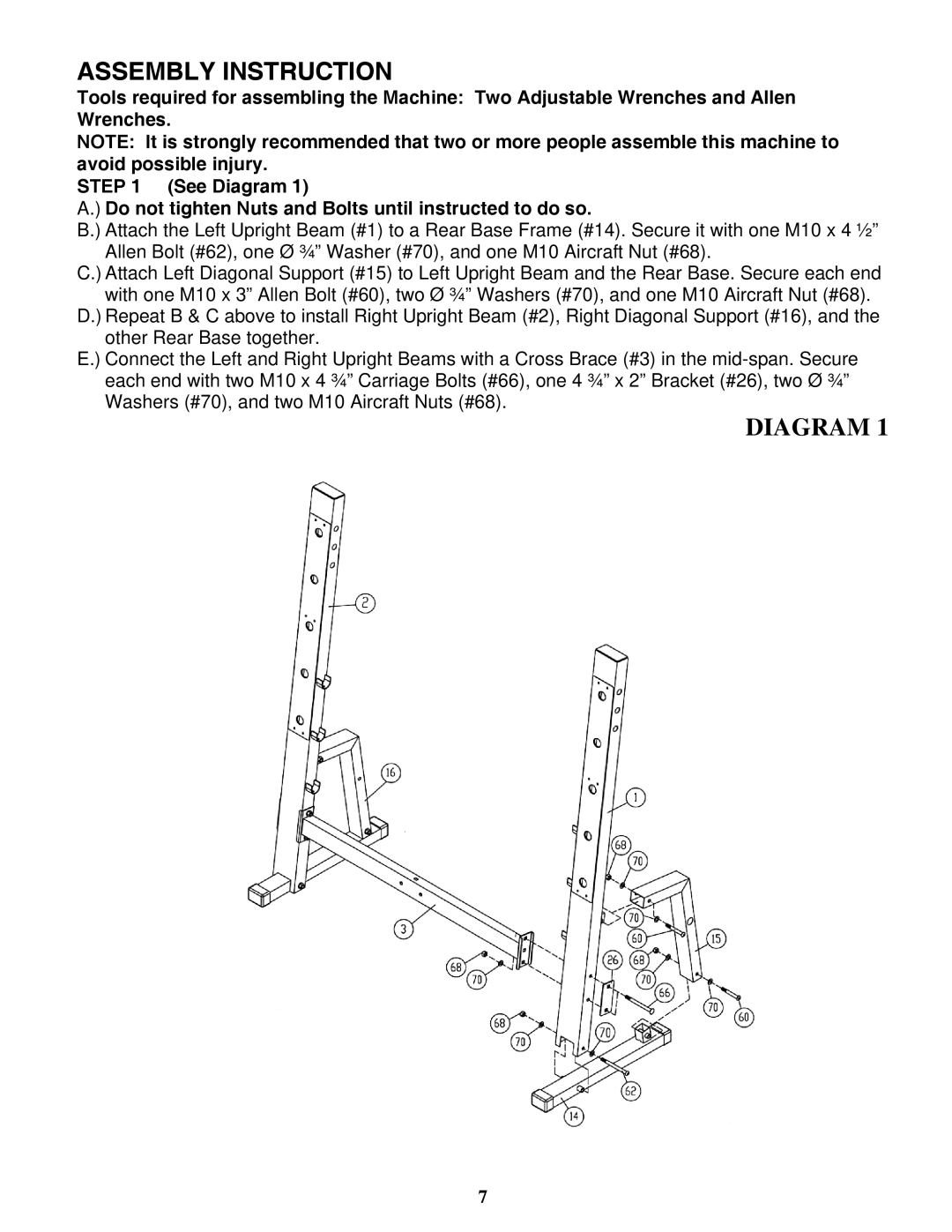
STEP 1 (See Diagram 1)
A.) Do not tighten Nuts and Bolts until instructed to do so.
B.) Attach the Left Upright Beam (#1) to a Rear Base Frame (#14). Secure it with one M10 x 4 ½” Allen Bolt (#62), one Ø ¾” Washer (#70), and one M10 Aircraft Nut (#68).
C.) Attach Left Diagonal Support (#15) to Left Upright Beam and the Rear Base. Secure each end with one M10 x 3” Allen Bolt (#60), two Ø ¾” Washers (#70), and one M10 Aircraft Nut (#68).
D.) Repeat B & C above to install Right Upright Beam (#2), Right Diagonal Support (#16), and the other Rear Base together.
E.) Connect the Left and Right Upright Beams with a Cross Brace (#3) in the
DIAGRAM 1
7