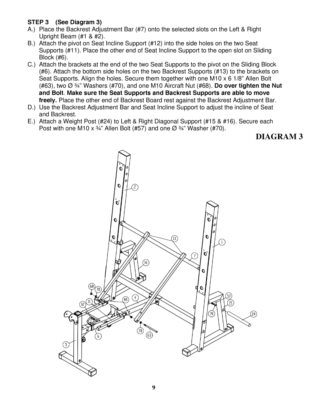
STEP 3 (See Diagram 3)
A.) Place the Backrest Adjustment Bar (#7) onto the selected slots on the Left & Right Upright Beam (#1 & #2).
B.) Attach the pivot on Seat Incline Support (#12) into the side holes on the two Seat Supports (#11). Place the other end of Seat Incline Support to the open slot on Sliding Block (#6).
C.) Attach the brackets at the end of the two Seat Supports to the pivot on the Sliding Block (#6). Attach the bottom side holes on the two Backrest Supports (#13) to the brackets on Seat Supports. Align the holes. Secure them together with one M10 x 6 1/8” Allen Bolt (#63), two Ø ¾” Washers (#70), and one M10 Aircraft Nut (#68). Do over tighten the Nut and Bolt. Make sure the Seat Supports and Backrest Supports are able to move freely. Place the other end of Backrest Board rest against the Backrest Adjustment Bar.
D.) Use the Backrest Adjustment Bar and Seat Incline Support to adjust the incline of Seat and Backrest.
E.) Attach a Weight Post (#24) to Left & Right Diagonal Support (#15 & #16). Secure each Post with one M10 x ¾” Allen Bolt (#57) and one Ø ¾” Washer (#70).
DIAGRAM 3
9