STEP 2 (See Diagram 2)
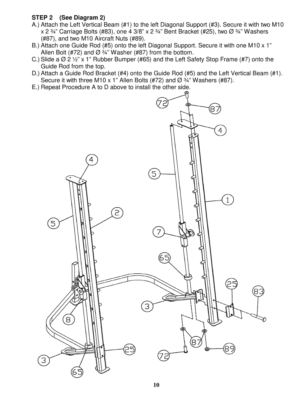
A.) Attach the Left Vertical Beam (#1) to the left Diagonal Support (#3). Secure it with two M10 x 2 ¾” Carriage Bolts (#83), one 4 3/8” x 2 ¾” Bent Bracket (#25), two Ø ¾” Washers (#87), and two M10 Aircraft Nuts (#89).
B.) Attach one Guide Rod (#5) onto the left Diagonal Support. Secure it with one M10 x 1” Allen Bolt (#72) and Ø ¾” Washer (#87) from the bottom.
C.) Slide a Ø 2 ½” x 1” Rubber Bumper (#65) and the Left Safety Stop Frame (#7) onto the Guide Rod from the top.
D.) Attach a Guide Rod Bracket (#4) onto the Guide Rod (#5) and the Left Vertical Beam (#1). Secure it with three M10 x 1” Allen Bolts (#72) and Ø ¾” Washers (#87).
E.) Repeat Procedure A to D above to install the other side.
10