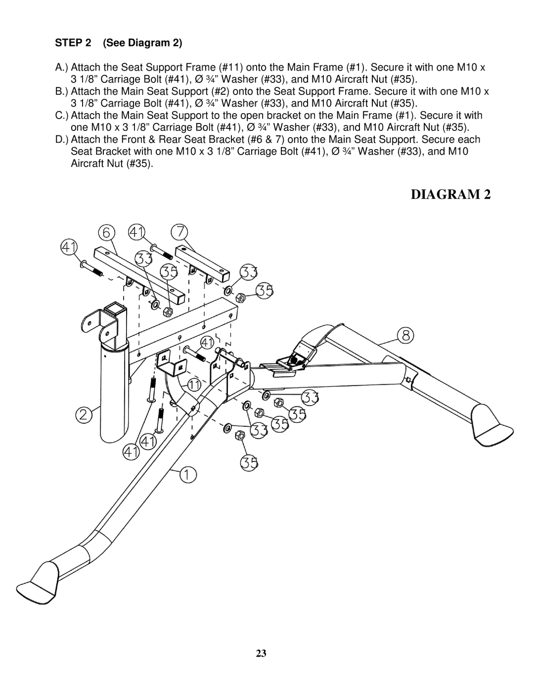
STEP 2 (See Diagram 2)
A.) Attach the Seat Support Frame (#11) onto the Main Frame (#1). Secure it with one M10 x 3 1/8” Carriage Bolt (#41), Ø ¾” Washer (#33), and M10 Aircraft Nut (#35).
B.) Attach the Main Seat Support (#2) onto the Seat Support Frame. Secure it with one M10 x 3 1/8” Carriage Bolt (#41), Ø ¾” Washer (#33), and M10 Aircraft Nut (#35).
C.) Attach the Main Seat Support to the open bracket on the Main Frame (#1). Secure it with one M10 x 3 1/8” Carriage Bolt (#41), Ø ¾” Washer (#33), and M10 Aircraft Nut (#35).
D.) Attach the Front & Rear Seat Bracket (#6 & 7) onto the Main Seat Support. Secure each Seat Bracket with one M10 x 3 1/8” Carriage Bolt (#41), Ø ¾” Washer (#33), and M10 Aircraft Nut (#35).
DIAGRAM 2
23