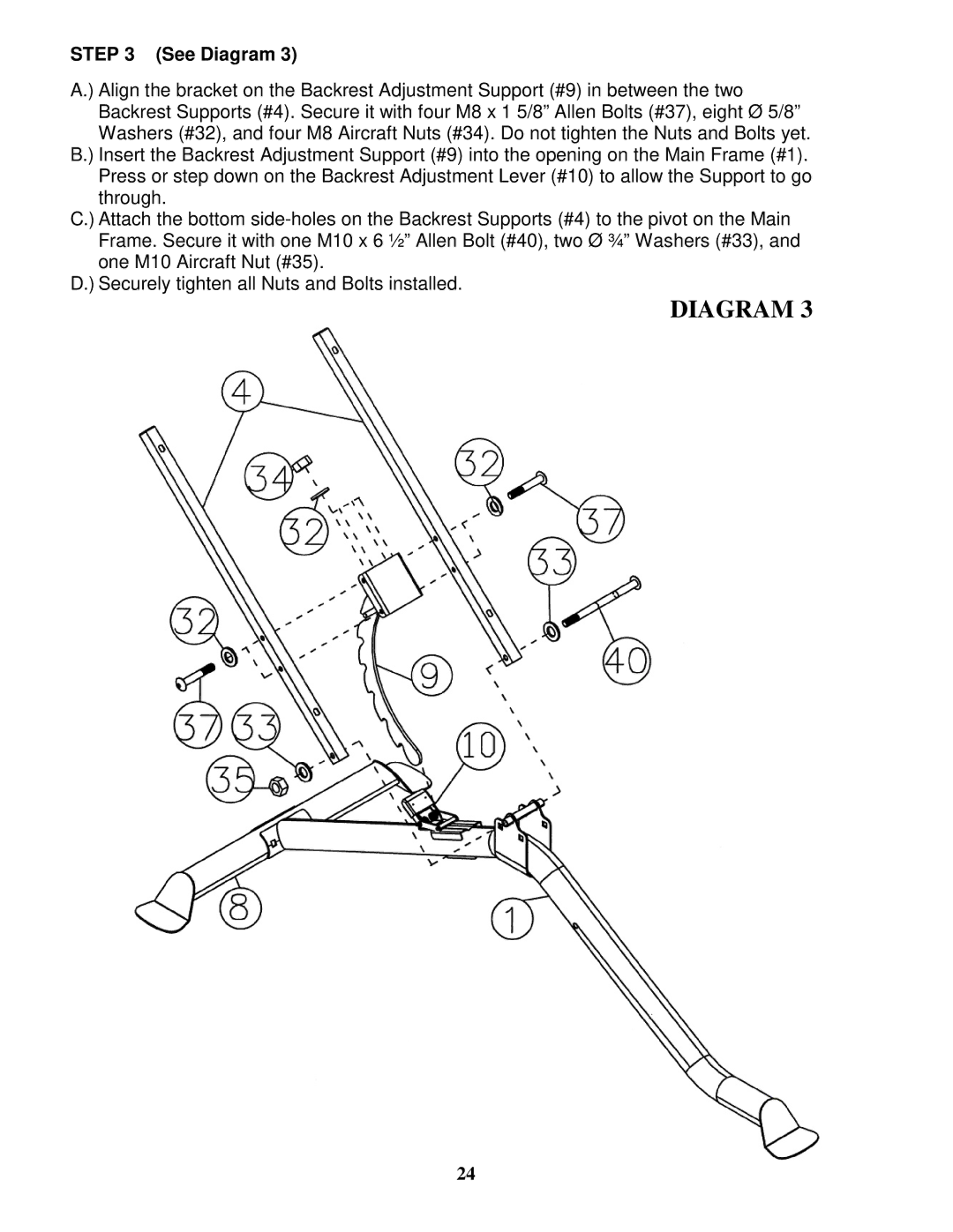
STEP 3 (See Diagram 3)
A.) Align the bracket on the Backrest Adjustment Support (#9) in between the two Backrest Supports (#4). Secure it with four M8 x 1 5/8” Allen Bolts (#37), eight Ø 5/8” Washers (#32), and four M8 Aircraft Nuts (#34). Do not tighten the Nuts and Bolts yet.
B.) Insert the Backrest Adjustment Support (#9) into the opening on the Main Frame (#1). Press or step down on the Backrest Adjustment Lever (#10) to allow the Support to go through.
C.) Attach the bottom
D.) Securely tighten all Nuts and Bolts installed.
DIAGRAM 3
24