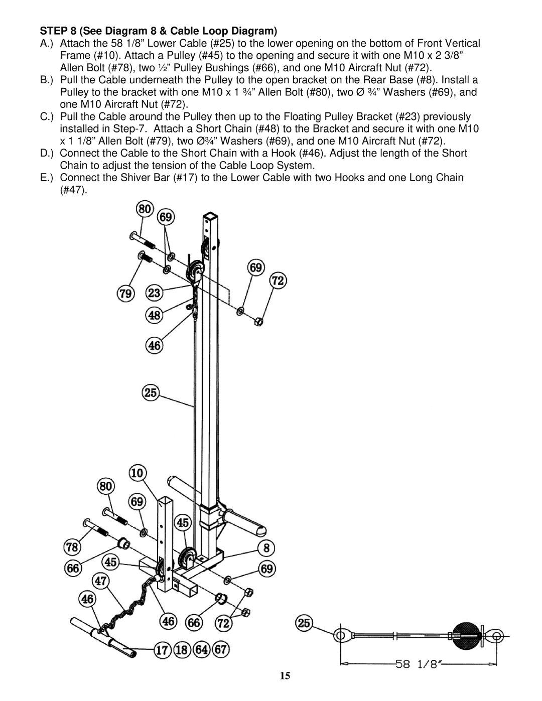
STEP 8 (See Diagram 8 & Cable Loop Diagram)
A.) Attach the 58 1/8” Lower Cable (#25) to the lower opening on the bottom of Front Vertical Frame (#10). Attach a Pulley (#45) to the opening and secure it with one M10 x 2 3/8” Allen Bolt (#78), two ½” Pulley Bushings (#66), and one M10 Aircraft Nut (#72).
B.) Pull the Cable underneath the Pulley to the open bracket on the Rear Base (#8). Install a Pulley to the bracket with one M10 x 1 ¾” Allen Bolt (#80), two Ø ¾” Washers (#69), and one M10 Aircraft Nut (#72).
C.) Pull the Cable around the Pulley then up to the Floating Pulley Bracket (#23) previously installed in
D.) Connect the Cable to the Short Chain with a Hook (#46). Adjust the length of the Short Chain to adjust the tension of the Cable Loop System.
E.) Connect the Shiver Bar (#17) to the Lower Cable with two Hooks and one Long Chain (#47).
15