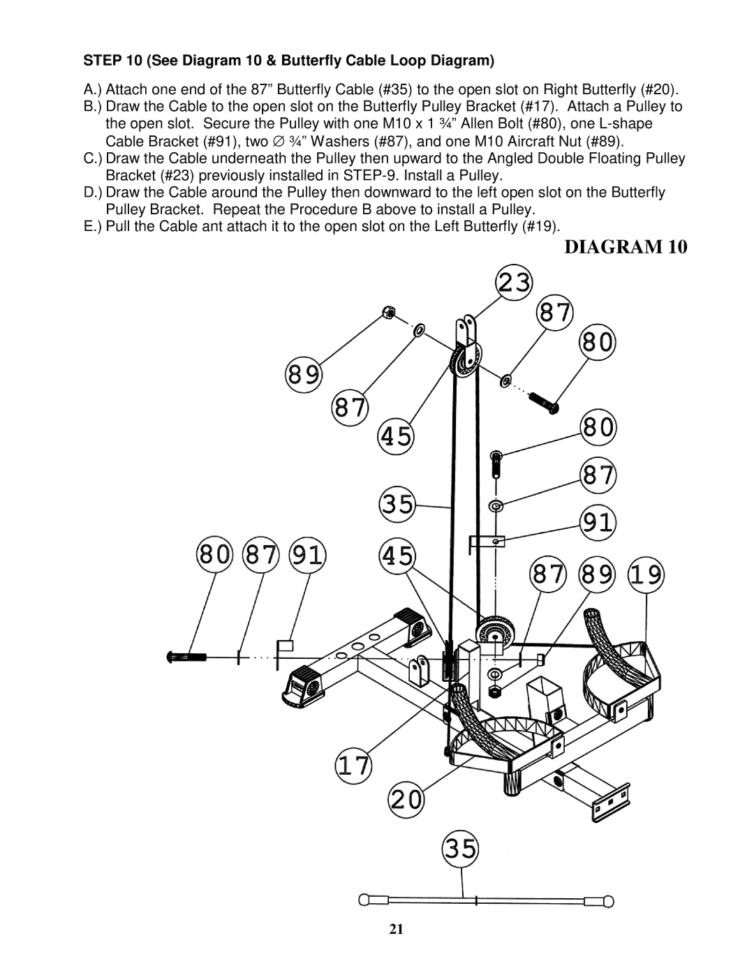
STEP 10 (See Diagram 10 & Butterfly Cable Loop Diagram)
A.) Attach one end of the 87” Butterfly Cable (#35) to the open slot on Right Butterfly (#20). B.) Draw the Cable to the open slot on the Butterfly Pulley Bracket (#17). Attach a Pulley to the open slot. Secure the Pulley with one M10 x 1 ¾” Allen Bolt (#80), one
Cable Bracket (#91), two ∅ ¾” Washers (#87), and one M10 Aircraft Nut (#89).
C.) Draw the Cable underneath the Pulley then upward to the Angled Double Floating Pulley Bracket (#23) previously installed in
D.) Draw the Cable around the Pulley then downward to the left open slot on the Butterfly Pulley Bracket. Repeat the Procedure B above to install a Pulley.
E.) Pull the Cable ant attach it to the open slot on the Left Butterfly (#19).
DIAGRAM 10
21