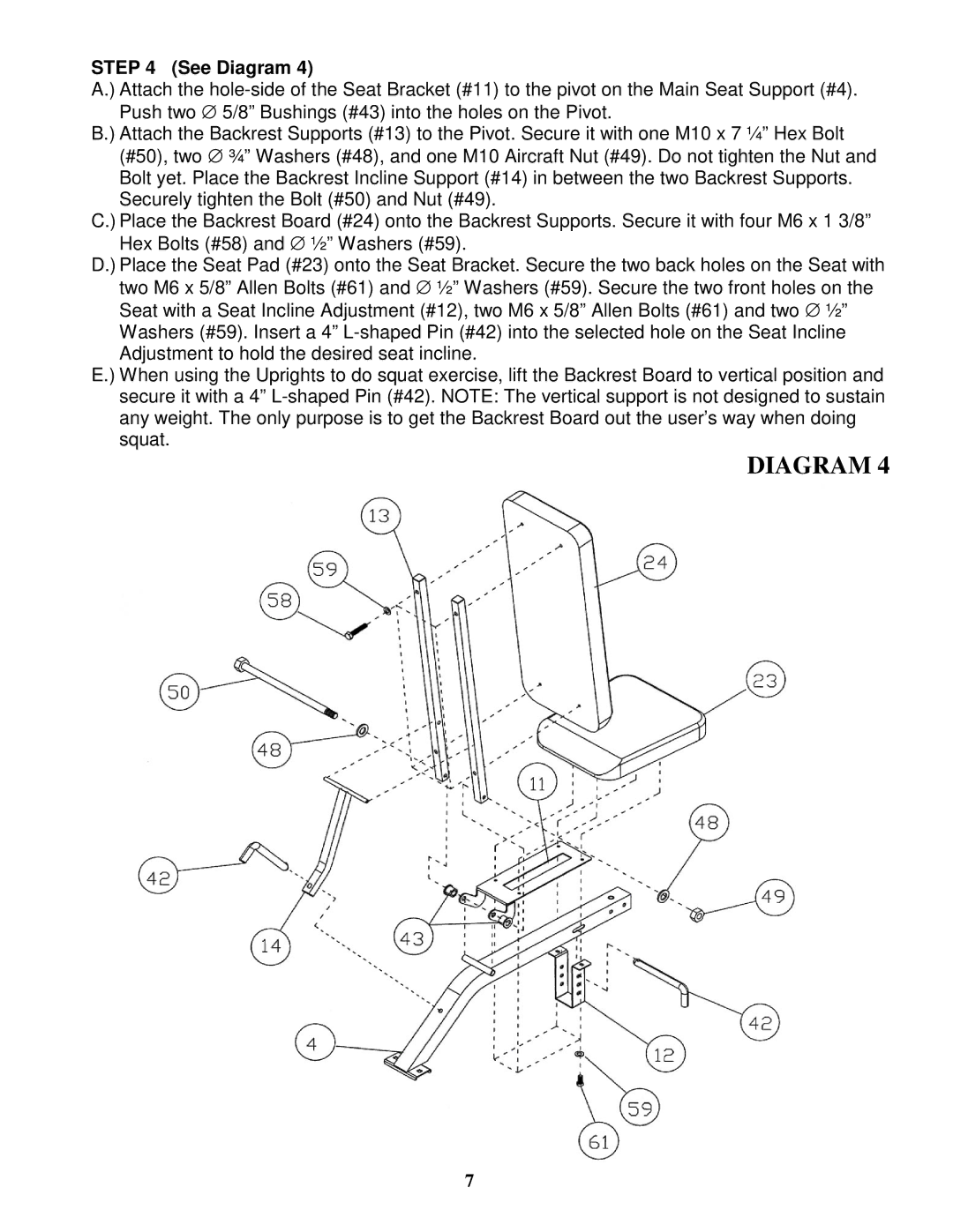
STEP 4 (See Diagram 4)
A.) Attach the
B.) Attach the Backrest Supports (#13) to the Pivot. Secure it with one M10 x 7 ¼” Hex Bolt (#50), two ∅ ¾” Washers (#48), and one M10 Aircraft Nut (#49). Do not tighten the Nut and Bolt yet. Place the Backrest Incline Support (#14) in between the two Backrest Supports. Securely tighten the Bolt (#50) and Nut (#49).
C.) Place the Backrest Board (#24) onto the Backrest Supports. Secure it with four M6 x 1 3/8” Hex Bolts (#58) and ∅ ½” Washers (#59).
D.) Place the Seat Pad (#23) onto the Seat Bracket. Secure the two back holes on the Seat with two M6 x 5/8” Allen Bolts (#61) and ∅ ½” Washers (#59). Secure the two front holes on the Seat with a Seat Incline Adjustment (#12), two M6 x 5/8” Allen Bolts (#61) and two ∅ ½” Washers (#59). Insert a 4”
E.) When using the Uprights to do squat exercise, lift the Backrest Board to vertical position and secure it with a 4”
DIAGRAM 4
7