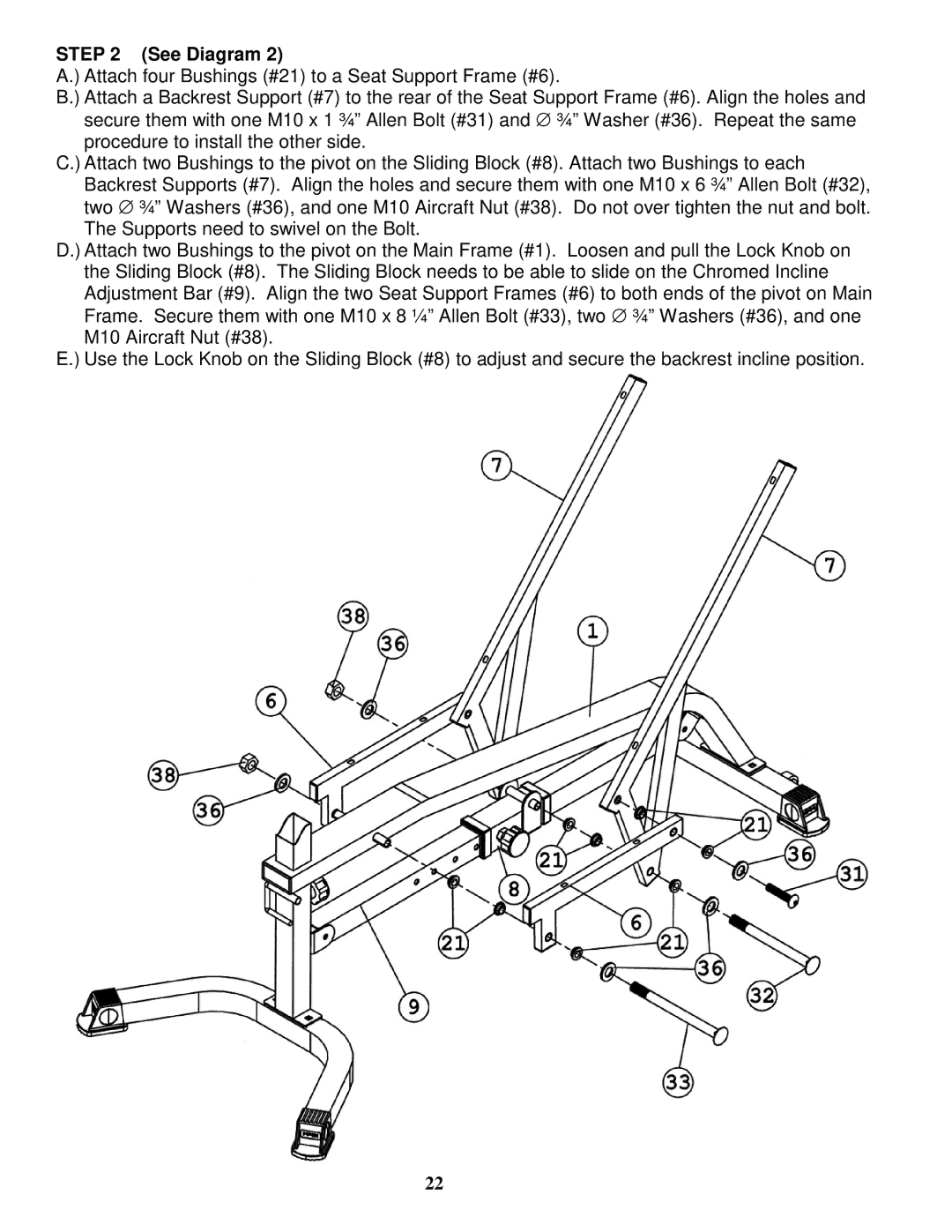
STEP 2 (See Diagram 2)
A.) Attach four Bushings (#21) to a Seat Support Frame (#6).
B.) Attach a Backrest Support (#7) to the rear of the Seat Support Frame (#6). Align the holes and secure them with one M10 x 1 ¾” Allen Bolt (#31) and ∅ ¾” Washer (#36). Repeat the same procedure to install the other side.
C.) Attach two Bushings to the pivot on the Sliding Block (#8). Attach two Bushings to each Backrest Supports (#7). Align the holes and secure them with one M10 x 6 ¾” Allen Bolt (#32), two ∅ ¾” Washers (#36), and one M10 Aircraft Nut (#38). Do not over tighten the nut and bolt. The Supports need to swivel on the Bolt.
D.) Attach two Bushings to the pivot on the Main Frame (#1). Loosen and pull the Lock Knob on the Sliding Block (#8). The Sliding Block needs to be able to slide on the Chromed Incline Adjustment Bar (#9). Align the two Seat Support Frames (#6) to both ends of the pivot on Main Frame. Secure them with one M10 x 8 ¼” Allen Bolt (#33), two ∅ ¾” Washers (#36), and one M10 Aircraft Nut (#38).
E.) Use the Lock Knob on the Sliding Block (#8) to adjust and secure the backrest incline position.
22