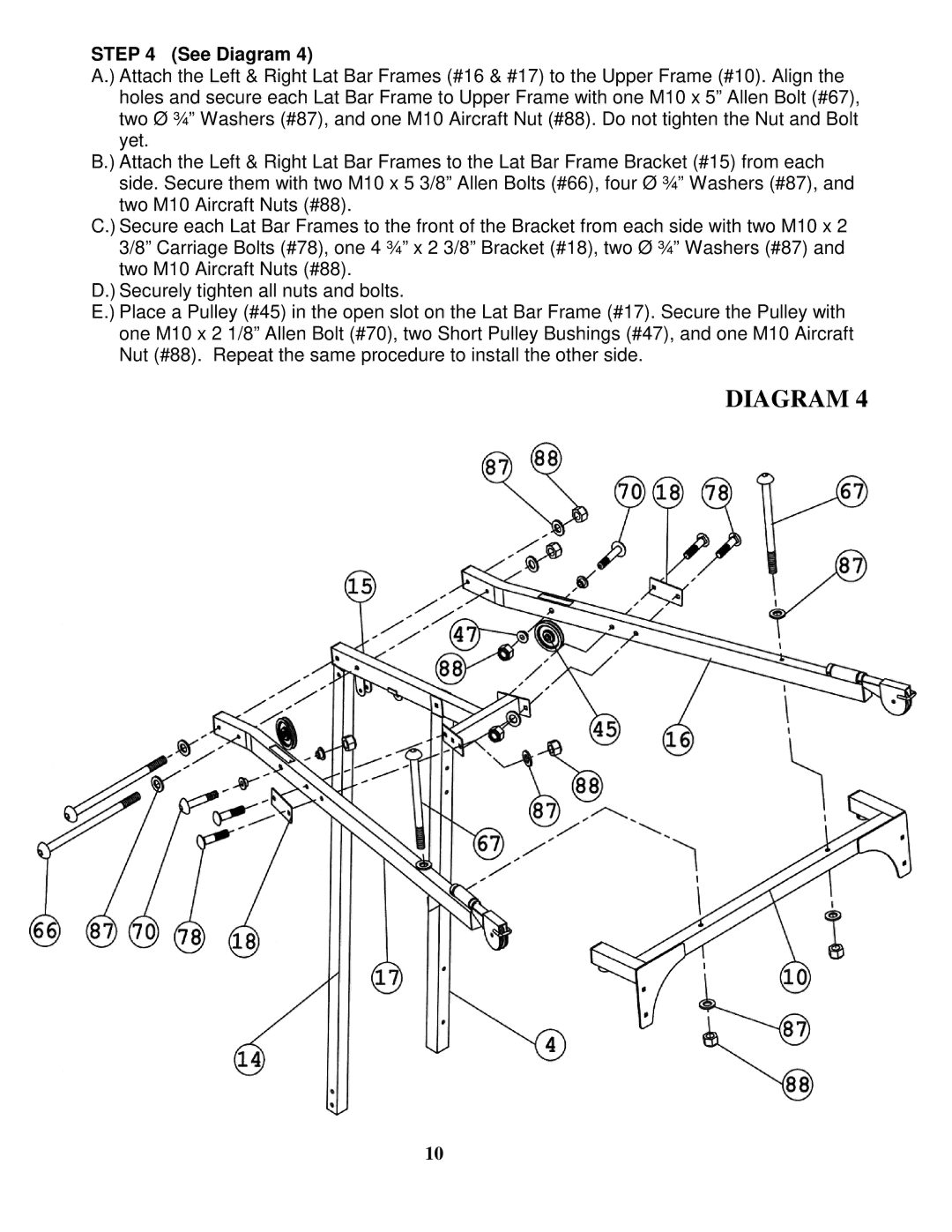
STEP 4 (See Diagram 4)
A.) Attach the Left & Right Lat Bar Frames (#16 & #17) to the Upper Frame (#10). Align the holes and secure each Lat Bar Frame to Upper Frame with one M10 x 5” Allen Bolt (#67), two Ø ¾” Washers (#87), and one M10 Aircraft Nut (#88). Do not tighten the Nut and Bolt yet.
B.) Attach the Left & Right Lat Bar Frames to the Lat Bar Frame Bracket (#15) from each side. Secure them with two M10 x 5 3/8” Allen Bolts (#66), four Ø ¾” Washers (#87), and two M10 Aircraft Nuts (#88).
C.) Secure each Lat Bar Frames to the front of the Bracket from each side with two M10 x 2 3/8” Carriage Bolts (#78), one 4 ¾” x 2 3/8” Bracket (#18), two Ø ¾” Washers (#87) and two M10 Aircraft Nuts (#88).
D.) Securely tighten all nuts and bolts.
E.) Place a Pulley (#45) in the open slot on the Lat Bar Frame (#17). Secure the Pulley with one M10 x 2 1/8” Allen Bolt (#70), two Short Pulley Bushings (#47), and one M10 Aircraft Nut (#88). Repeat the same procedure to install the other side.
DIAGRAM 4
10