STEP 9 (See Diagram 9)
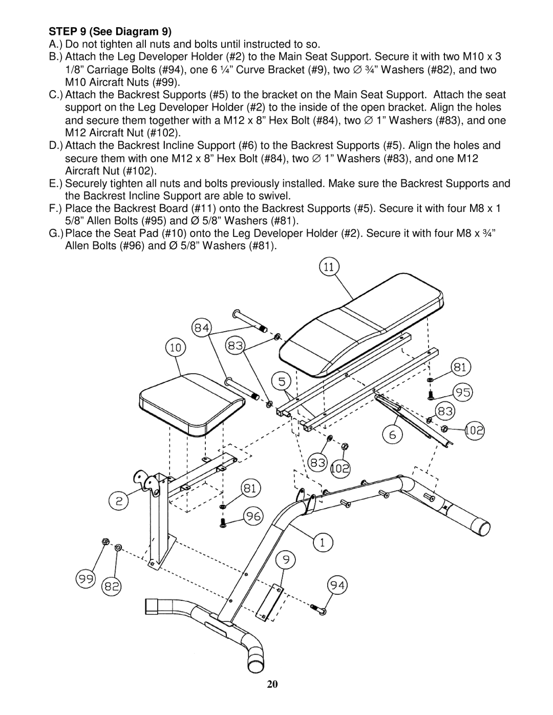
A.) Do not tighten all nuts and bolts until instructed to so.
B.) Attach the Leg Developer Holder (#2) to the Main Seat Support. Secure it with two M10 x 3 1/8” Carriage Bolts (#94), one 6 ¼” Curve Bracket (#9), two ∅ ¾” Washers (#82), and two M10 Aircraft Nuts (#99).
C.) Attach the Backrest Supports (#5) to the bracket on the Main Seat Support. Attach the seat support on the Leg Developer Holder (#2) to the inside of the open bracket. Align the holes and secure them together with a M12 x 8” Hex Bolt (#84), two ∅ 1” Washers (#83), and one M12 Aircraft Nut (#102).
D.) Attach the Backrest Incline Support (#6) to the Backrest Supports (#5). Align the holes and secure them with one M12 x 8” Hex Bolt (#84), two ∅ 1” Washers (#83), and one M12 Aircraft Nut (#102).
E.) Securely tighten all nuts and bolts previously installed. Make sure the Backrest Supports and the Backrest Incline Support are able to swivel.
F.) Place the Backrest Board (#11) onto the Backrest Supports (#5). Secure it with four M8 x 1 5/8” Allen Bolts (#95) and Ø 5/8” Washers (#81).
G.)Place the Seat Pad (#10) onto the Leg Developer Holder (#2). Secure it with four M8 x ¾” Allen Bolts (#96) and Ø 5/8” Washers (#81).
20