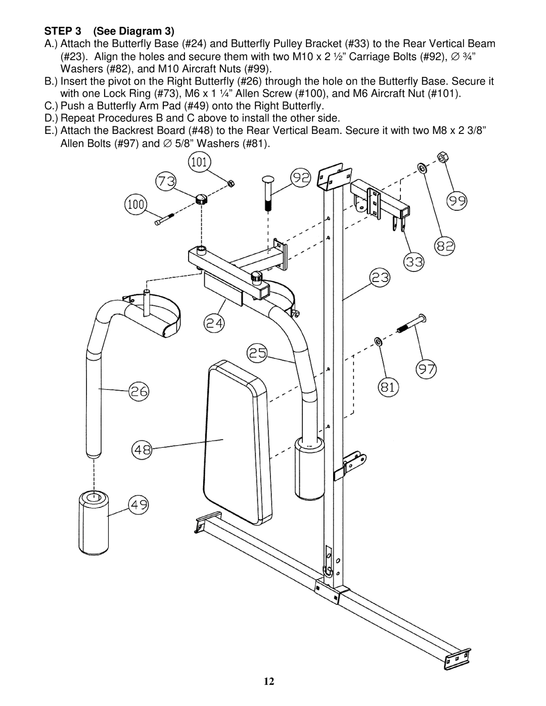
STEP 3 (See Diagram 3)
A.) Attach the Butterfly Base (#24) and Butterfly Pulley Bracket (#33) to the Rear Vertical Beam (#23). Align the holes and secure them with two M10 x 2 ½” Carriage Bolts (#92), ∅ ¾” Washers (#82), and M10 Aircraft Nuts (#99).
B.) Insert the pivot on the Right Butterfly (#26) through the hole on the Butterfly Base. Secure it with one Lock Ring (#73), M6 x 1 ¼” Allen Screw (#100), and M6 Aircraft Nut (#101).
C.) Push a Butterfly Arm Pad (#49) onto the Right Butterfly.
D.) Repeat Procedures B and C above to install the other side.
E.) Attach the Backrest Board (#48) to the Rear Vertical Beam. Secure it with two M8 x 2 3/8” Allen Bolts (#97) and ∅ 5/8” Washers (#81).
12