ASSEMBLY INSTRUCTION
Tools Required Assembling the Machine: Two Adjustable Wrenches and Allen Wrenches.
NOTE: It is strongly recommended this machine to be assembled by two or more people to avoid possible injury.
STEP 1 (See Diagram 1)
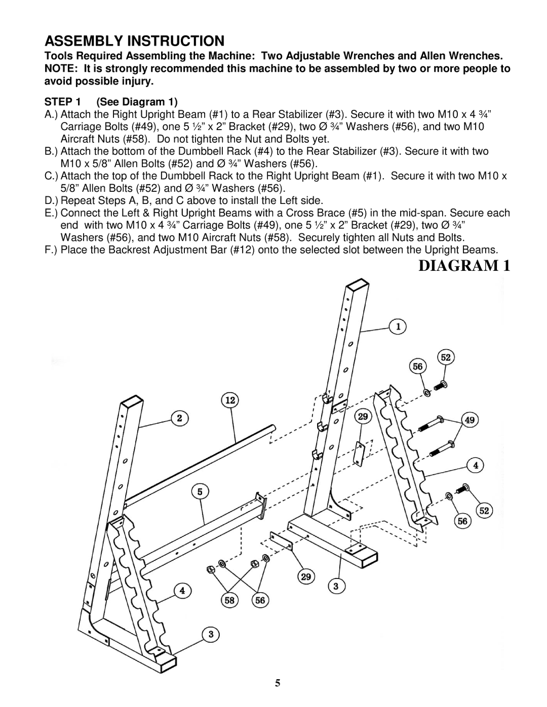
A.) Attach the Right Upright Beam (#1) to a Rear Stabilizer (#3). Secure it with two M10 x 4 ¾” Carriage Bolts (#49), one 5 ½” x 2” Bracket (#29), two Ø ¾” Washers (#56), and two M10 Aircraft Nuts (#58). Do not tighten the Nut and Bolts yet.
B.) Attach the bottom of the Dumbbell Rack (#4) to the Rear Stabilizer (#3). Secure it with two M10 x 5/8” Allen Bolts (#52) and Ø ¾” Washers (#56).
C.) Attach the top of the Dumbbell Rack to the Right Upright Beam (#1). Secure it with two M10 x 5/8” Allen Bolts (#52) and Ø ¾” Washers (#56).
D.) Repeat Steps A, B, and C above to install the Left side.
E.) Connect the Left & Right Upright Beams with a Cross Brace (#5) in the
F.) Place the Backrest Adjustment Bar (#12) onto the selected slot between the Upright Beams.
DIAGRAM 1
5