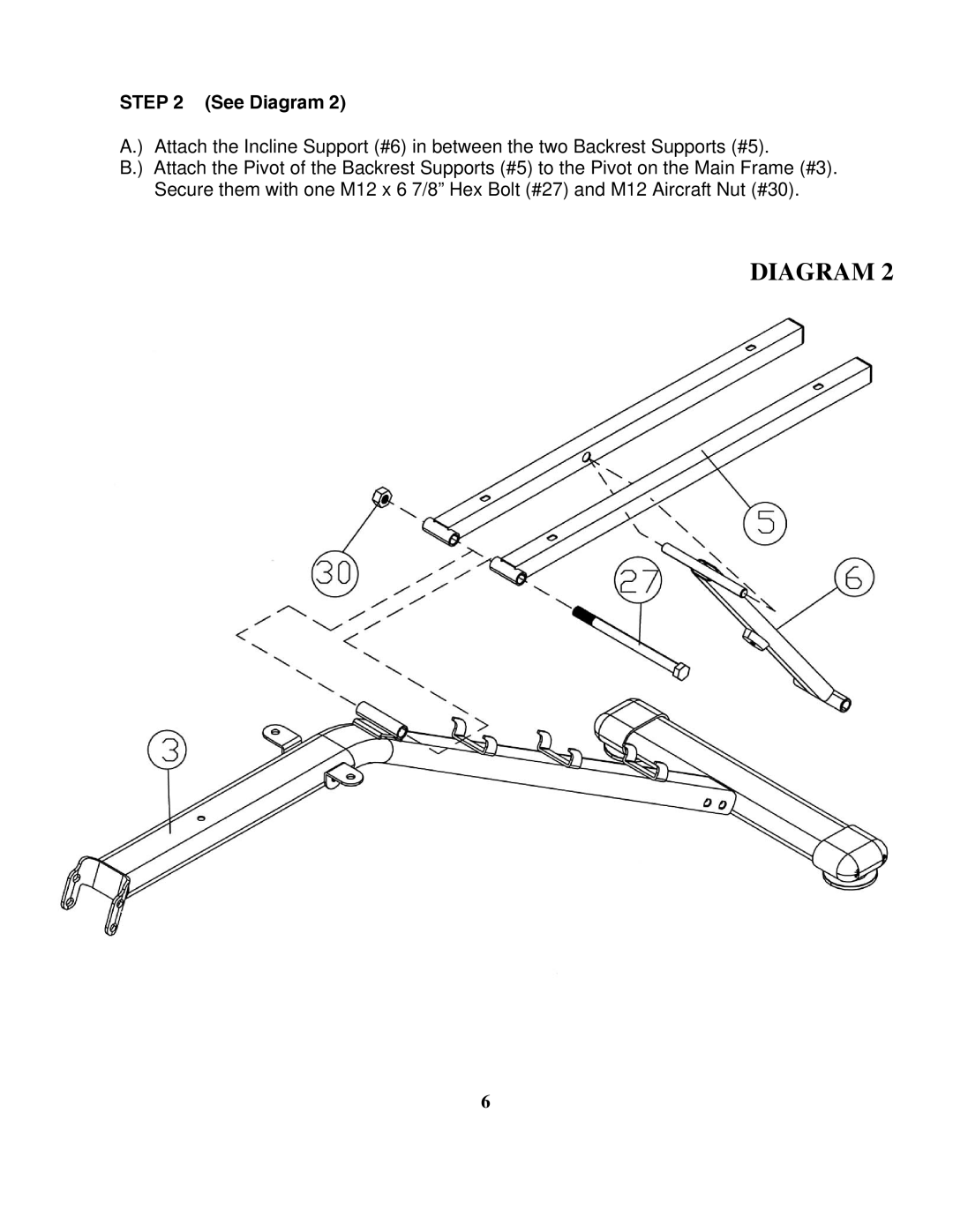
STEP 2 (See Diagram 2)
A.) Attach the Incline Support (#6) in between the two Backrest Supports (#5).
B.) Attach the Pivot of the Backrest Supports (#5) to the Pivot on the Main Frame (#3). Secure them with one M12 x 6 7/8” Hex Bolt (#27) and M12 Aircraft Nut (#30).
DIAGRAM 2
6