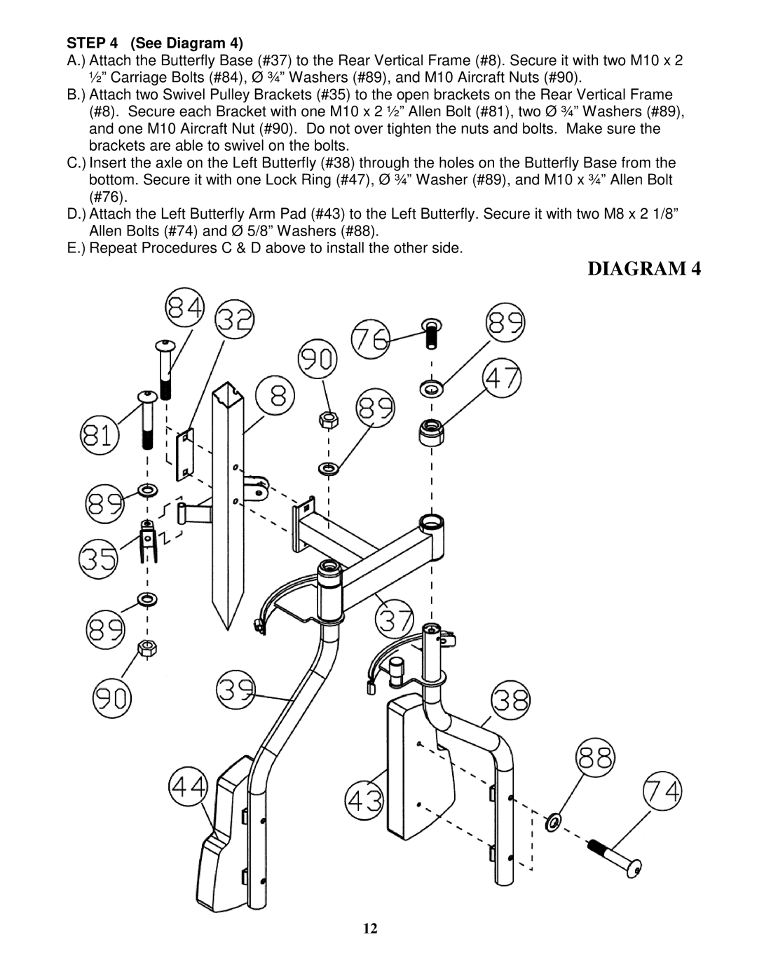
STEP 4 (See Diagram 4)
A.) Attach the Butterfly Base (#37) to the Rear Vertical Frame (#8). Secure it with two M10 x 2 ½” Carriage Bolts (#84), Ø ¾” Washers (#89), and M10 Aircraft Nuts (#90).
B.) Attach two Swivel Pulley Brackets (#35) to the open brackets on the Rear Vertical Frame (#8). Secure each Bracket with one M10 x 2 ½” Allen Bolt (#81), two Ø ¾” Washers (#89), and one M10 Aircraft Nut (#90). Do not over tighten the nuts and bolts. Make sure the brackets are able to swivel on the bolts.
C.) Insert the axle on the Left Butterfly (#38) through the holes on the Butterfly Base from the bottom. Secure it with one Lock Ring (#47), Ø ¾” Washer (#89), and M10 x ¾” Allen Bolt (#76).
D.) Attach the Left Butterfly Arm Pad (#43) to the Left Butterfly. Secure it with two M8 x 2 1/8” Allen Bolts (#74) and Ø 5/8” Washers (#88).
E.) Repeat Procedures C & D above to install the other side.
DIAGRAM 4
12
