ASSEMBLY INSTRUCTION
Tools Required Assembling the Machine: One Adjustable Wrench and Allen Wrench
NOTE: It is strongly recommended two or more people assembling the machine to avoid possible injury.
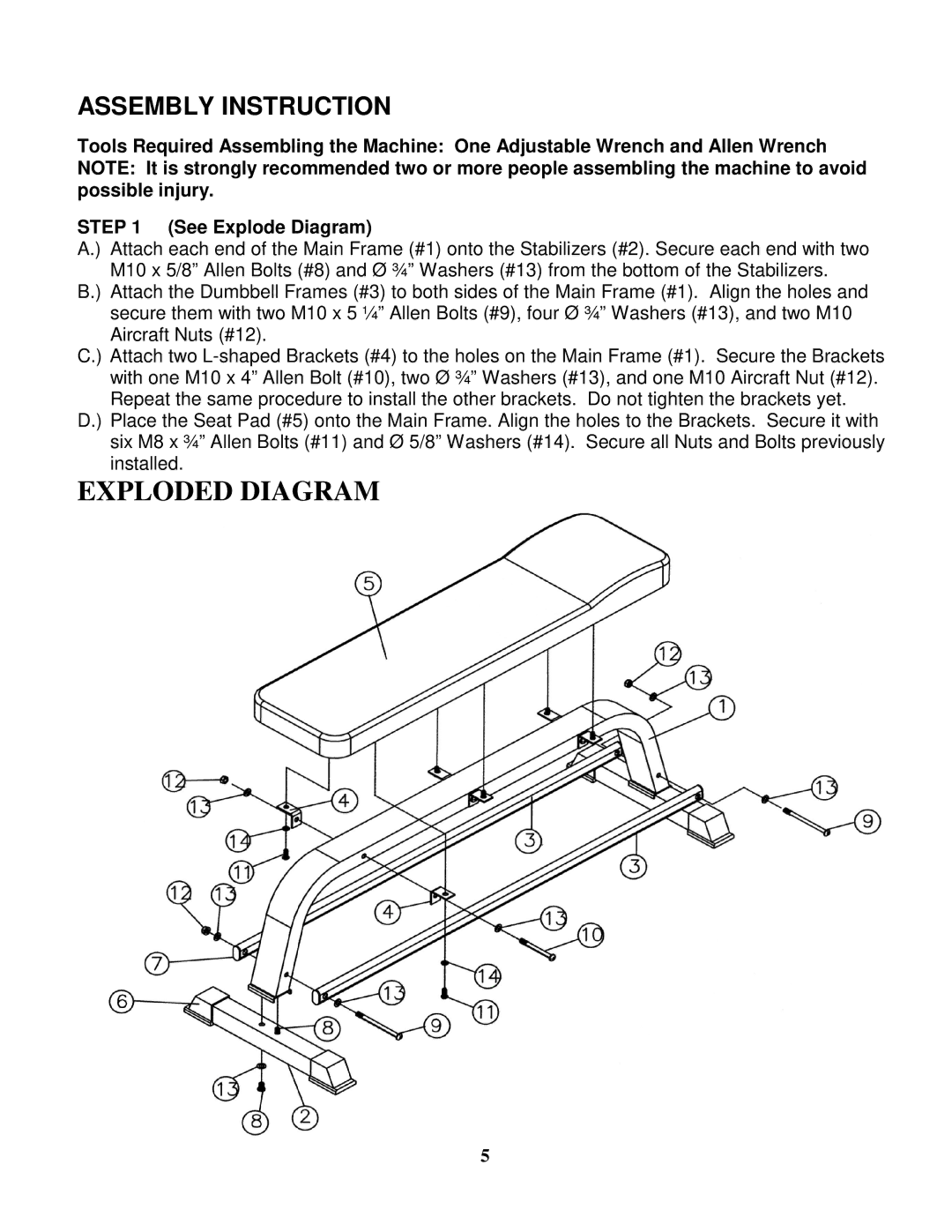
STEP 1 (See Explode Diagram)
A.) Attach each end of the Main Frame (#1) onto the Stabilizers (#2). Secure each end with two M10 x 5/8” Allen Bolts (#8) and Ø ¾” Washers (#13) from the bottom of the Stabilizers.
B.) Attach the Dumbbell Frames (#3) to both sides of the Main Frame (#1). Align the holes and secure them with two M10 x 5 ¼” Allen Bolts (#9), four Ø ¾” Washers (#13), and two M10 Aircraft Nuts (#12).
C.) Attach two
D.) Place the Seat Pad (#5) onto the Main Frame. Align the holes to the Brackets. Secure it with six M8 x ¾” Allen Bolts (#11) and Ø 5/8” Washers (#14). Secure all Nuts and Bolts previously installed.
EXPLODED DIAGRAM
5