ASSEMBLY INSTRUCTION
Tools required assembling the machine: Two Adjustable Wrenches.
NOTE: It is strongly recommended two or more people assembling this equipment to avoid possible injury.
STEP 1 (See Diagram 1)
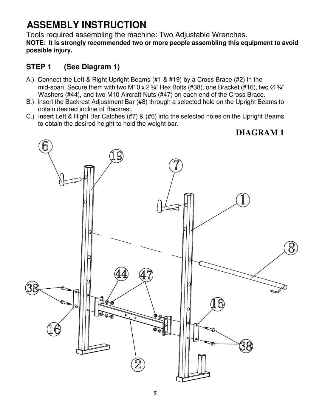
A.) Connect the Left & Right Upright Beams (#1 & #19) by a Cross Brace (#2) in the
B.) Insert the Backrest Adjustment Bar (#8) through a selected hole on the Upright Beams to obtain desired incline of Backrest.
C.) Insert Left & Right Bar Catches (#7) & (#6) into the selected holes on the Upright Beams to obtain the desired height to hold the weight bar.
DIAGRAM 1
5