STEP 2 (See Diagram 2)
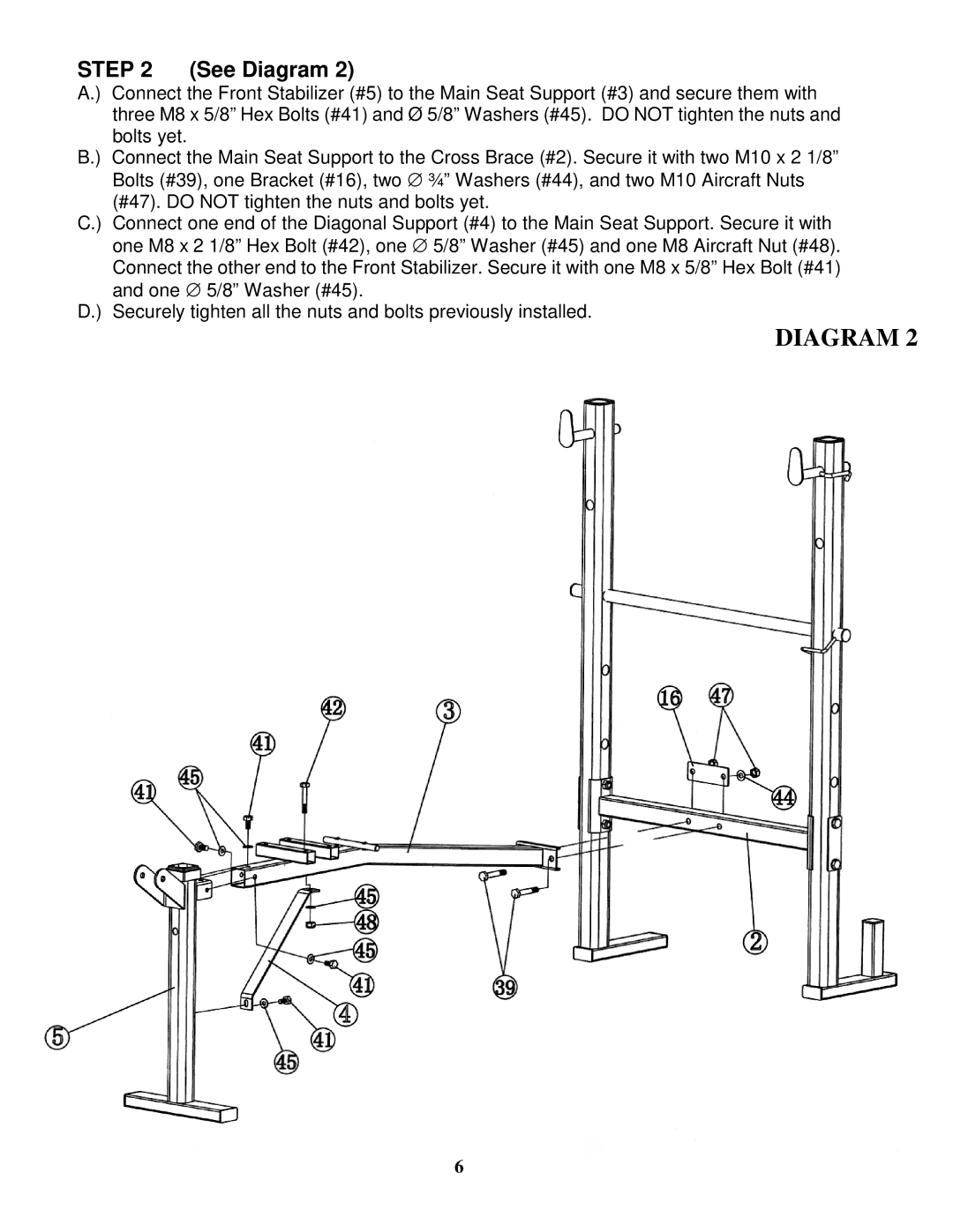
A.) Connect the Front Stabilizer (#5) to the Main Seat Support (#3) and secure them with three M8 x 5/8” Hex Bolts (#41) and Ø 5/8” Washers (#45). DO NOT tighten the nuts and bolts yet.
B.) Connect the Main Seat Support to the Cross Brace (#2). Secure it with two M10 x 2 1/8”
Bolts (#39), one Bracket (#16), two ∅ ¾” Washers (#44), and two M10 Aircraft Nuts (#47). DO NOT tighten the nuts and bolts yet.
C.) Connect one end of the Diagonal Support (#4) to the Main Seat Support. Secure it with one M8 x 2 1/8” Hex Bolt (#42), one ∅ 5/8” Washer (#45) and one M8 Aircraft Nut (#48). Connect the other end to the Front Stabilizer. Secure it with one M8 x 5/8” Hex Bolt (#41) and one ∅ 5/8” Washer (#45).
D.) Securely tighten all the nuts and bolts previously installed.
DIAGRAM 2
6