ASSEMBLY INSTRUCTION
Tools required to assembly the machine:
Two Adjustable Wrenches and Two Allen Wrenches
STEP 1 (SEE Diagram 1)
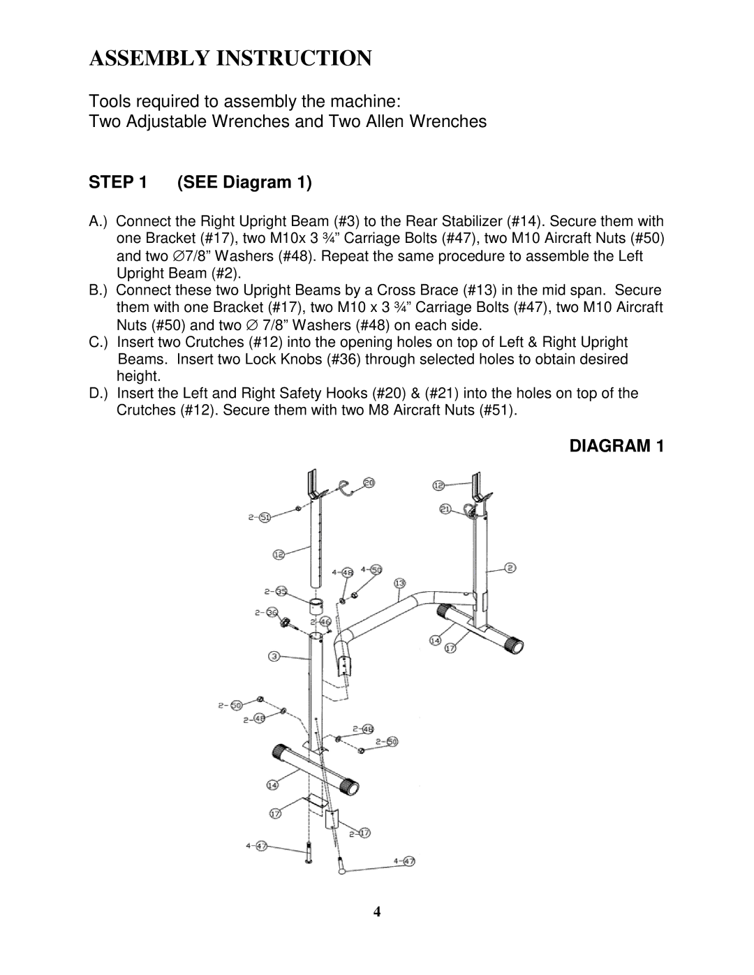
A.) Connect the Right Upright Beam (#3) to the Rear Stabilizer (#14). Secure them with one Bracket (#17), two M10x 3 ¾” Carriage Bolts (#47), two M10 Aircraft Nuts (#50) and two ∅ 7/8” Washers (#48). Repeat the same procedure to assemble the Left Upright Beam (#2).
B.) Connect these two Upright Beams by a Cross Brace (#13) in the mid span. Secure them with one Bracket (#17), two M10 x 3 ¾” Carriage Bolts (#47), two M10 Aircraft Nuts (#50) and two ∅ 7/8” Washers (#48) on each side.
C.) Insert two Crutches (#12) into the opening holes on top of Left & Right Upright Beams. Insert two Lock Knobs (#36) through selected holes to obtain desired height.
D.) Insert the Left and Right Safety Hooks (#20) & (#21) into the holes on top of the Crutches (#12). Secure them with two M8 Aircraft Nuts (#51).
DIAGRAM 1
4