b)Oven burner
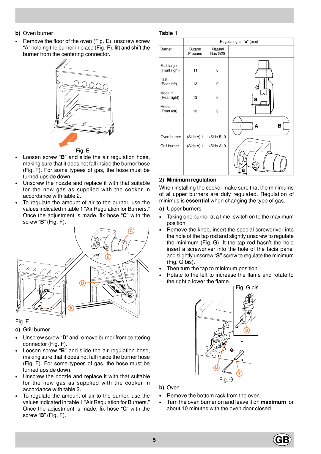
∙Remove the floor of the oven (Fig. E), unscrew screw “A” holding the burner in place (Fig. F), lift and shift the burner from the centering connector.
Fig. E
∙Loosen screw “B” and slide the air regulation hose, making sure that it does not fall inside the burner hose (Fig. F). For some typees of gas, the hose must be turned upside down.
∙Unscrew the nozzle and replace it with that suitable for the new gas as supplied with the cooker in accordance with table 2.
∙To regulate the amount of air to the burner, use the values indicated in table 1 “Air Regulation for Burners.” Once the adjustment is made, fix hose “C” with the screw “B” (Fig. F).
C
B
D ![]()
![]()
![]() A
A
Table 1
|
| Regulating air "a" (mm) | ||||||||||
Burner | Butane | Natural |
|
|
|
|
|
|
|
|
|
|
| Propane | Gas G20 |
|
|
|
|
|
|
|
|
|
|
|
|
|
|
|
|
|
|
|
|
|
|
|
Fast large |
|
|
|
|
|
|
|
|
|
|
|
|
|
|
|
|
|
|
|
|
|
|
|
| |
|
|
|
|
|
|
|
|
|
|
|
| |
(Front right) | 11 | 0 |
|
|
|
|
|
|
|
|
|
|
|
|
|
|
|
|
|
|
|
| |||
Fast |
|
|
|
|
|
|
|
|
|
|
|
|
(Rear left) | 13 | 0 |
|
|
|
|
|
|
|
|
|
|
Medium |
|
|
|
|
|
|
|
|
|
|
|
|
|
|
|
|
|
|
|
|
|
|
|
| |
(Rear right) | 13 | 0 |
| a | ||||||||
|
|
|
| |||||||||
Medium |
|
|
|
|
|
|
|
|
|
|
|
|
|
|
|
|
|
|
|
|
|
|
|
| |
(Front left) | 13 | 0 |
|
|
|
|
|
|
|
|
|
|
![]() A B
A B ![]()
Oven burner | (Side A) 1 | (Side B) 0 |
Grill burner | (Side A) 1 | (Side A) 0 |
a
2) Minimum regulation
When installing the cooker make sure that the minimums of al upper burners are duly regulated. Regulation of minimus is essential when changing the type of gas.
a)Upper burners
∙Taking one burner at a time, switch on to the maximum position.
∙Remove the knob, insert the special screwdriver into the hole of the tap rod and slightly unscrew to regulate the minimum (Fig. G). It the tap rod hasn’t the hole insert a screwdriver into the hole of the facia panel and slightly unscrew “S” screw to regulate the minimum (Fig. G bis).
∙Then turn the tap to minimum position.
∙Rotate to the left to increase the flame and rotate to the right o lower the flame.
Fig. G bis
Fig. F
c)Grill burner
∙Unscrew screw “D” and remove burner from centering connector (Fig. F).
∙Loosen screw “B” and slide the air regulation hose, making sure that it does not fall inside the burner hose (Fig. F). For some typees of gas, the hose must be turned upside down.
∙Unscrew the nozzle and replace it with that suitable for the new gas as supplied with the cooker in accordance with table 2.
∙To regulate the amount of air to the burner, use the values indicated in table 1 “Air Regulation for Burners.” Once the adjustment is made, fix hose “C” with the screw “B” (Fig. F).
S
M
T
Fig. G
b)Oven
∙Remove the bottom rack from the oven.
∙Turn the oven burner on and leave it on maximum for about 10 minutes with the oven door closed.
5
