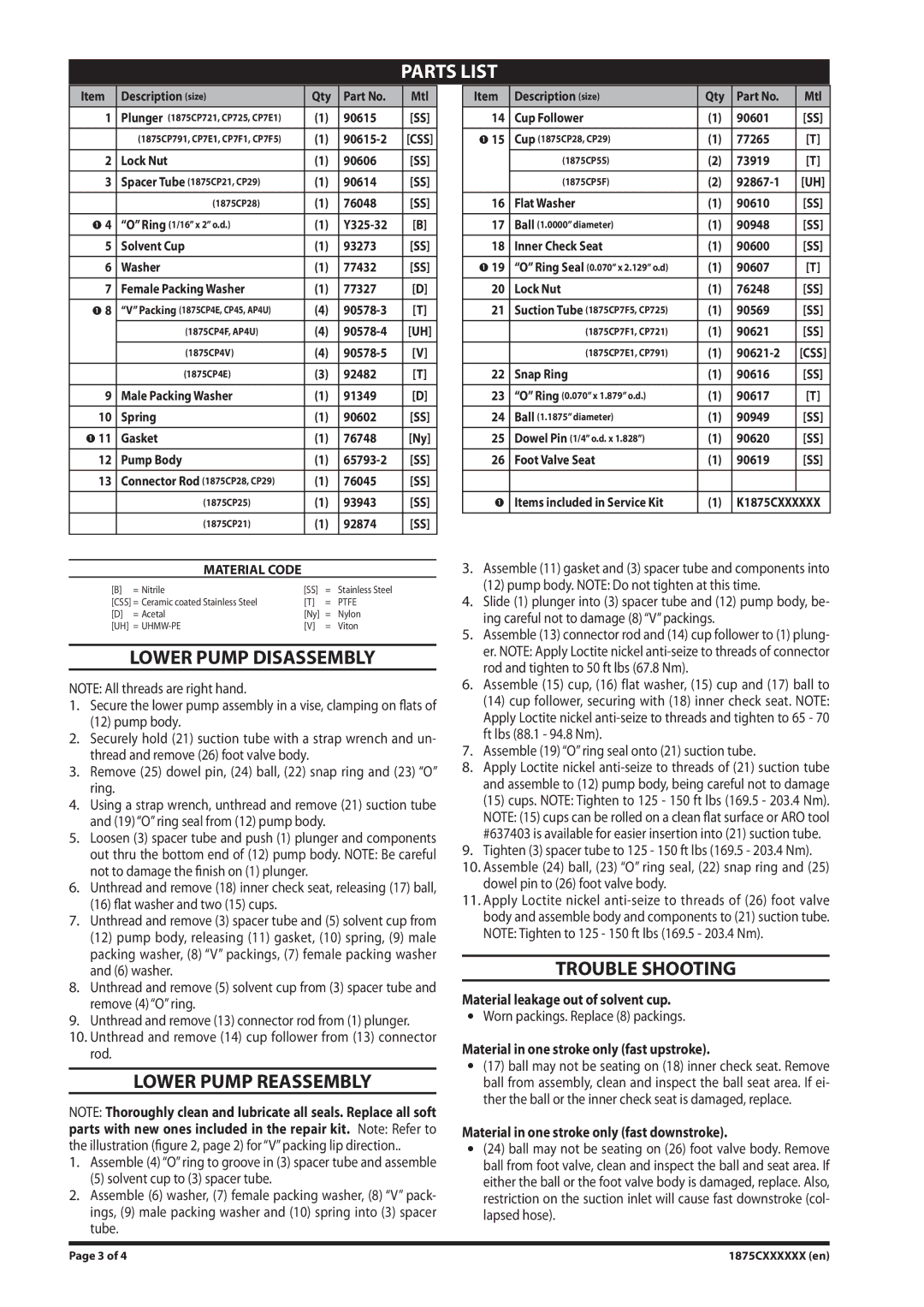
PARTS LIST
Item | Description (size) | Qty | Part No. | Mtl |
|
|
|
|
|
1 | Plunger (1875CP721, CP725, CP7E1) | (1) | 90615 | [SS] |
|
|
|
|
|
| (1875CP791, CP7E1, CP7F1, CP7F5) | (1) | [CSS] | |
2 | Lock Nut | (1) | 90606 | [SS] |
|
|
|
|
|
3 | Spacer Tube (1875CP21, CP29) | (1) | 90614 | [SS] |
|
|
|
|
|
| (1875CP28) | (1) | 76048 | [SS] |
|
|
|
|
|
4 | “O” Ring (1/16” x 2” o.d.) | (1) | [B] | |
|
|
|
|
|
5 | Solvent Cup | (1) | 93273 | [SS] |
|
|
|
|
|
6 | Washer | (1) | 77432 | [SS] |
|
|
|
|
|
7 | Female Packing Washer | (1) | 77327 | [D] |
|
|
|
|
|
8 | “V” Packing (1875CP4E, CP45, AP4U) | (4) | [T] | |
| (1875CP4F, AP4U) | (4) | [UH] | |
|
|
|
|
|
| (1875CP4V) | (4) | [V] | |
|
|
|
|
|
| (1875CP4E) | (3) | 92482 | [T] |
|
|
|
|
|
9 | Male Packing Washer | (1) | 91349 | [D] |
|
|
|
|
|
10 | Spring | (1) | 90602 | [SS] |
|
|
|
|
|
11 | Gasket | (1) | 76748 | [Ny] |
|
|
|
|
|
12 | Pump Body | (1) | [SS] | |
|
|
|
|
|
13 | Connector Rod (1875CP28, CP29) | (1) | 76045 | [SS] |
|
|
|
|
|
| (1875CP25) | (1) | 93943 | [SS] |
|
|
|
|
|
| (1875CP21) | (1) | 92874 | [SS] |
|
|
|
|
|
MATERIAL CODE
[B] | = Nitrile | [SS] | = | Stainless Steel |
[CSS] = Ceramic coated Stainless Steel | [T] | = | PTFE | |
[D] | = Acetal | [Ny] | = | Nylon |
[UH] | = | [V] | = | Viton |
LOWER PUMP DISASSEMBLY
NOTE: All threads are right hand.
1.Secure the lower pump assembly in a vise, clamping on flats of
(12)pump body.
2.Securely hold (21) suction tube with a strap wrench and un- thread and remove (26) foot valve body.
3.Remove (25) dowel pin, (24) ball, (22) snap ring and (23) “O” ring.
4.Using a strap wrench, unthread and remove (21) suction tube and (19) “O” ring seal from (12) pump body.
5.Loosen (3) spacer tube and push (1) plunger and components out thru the bottom end of (12) pump body. NOTE: Be careful not to damage the finish on (1) plunger.
6.Unthread and remove (18) inner check seat, releasing (17) ball,
(16)flat washer and two (15) cups.
7.Unthread and remove (3) spacer tube and (5) solvent cup from
(12)pump body, releasing (11) gasket, (10) spring, (9) male packing washer, (8) “V” packings, (7) female packing washer and (6) washer.
8.Unthread and remove (5) solvent cup from (3) spacer tube and remove (4) “O” ring.
9.Unthread and remove (13) connector rod from (1) plunger.
10.Unthread and remove (14) cup follower from (13) connector rod.
LOWER PUMP REASSEMBLY
NOTE: Thoroughly clean and lubricate all seals. Replace all soft
parts with new ones included in the repair kit. Note: Refer to the illustration (figure 2, page 2) for “V” packing lip direction..
1.Assemble (4) “O” ring to groove in (3) spacer tube and assemble
(5) solvent cup to (3) spacer tube.
2.Assemble (6) washer, (7) female packing washer, (8) “V” pack- ings, (9) male packing washer and (10) spring into (3) spacer tube.
Item | Description (size) | Qty | Part No. | Mtl |
|
|
|
|
|
14 | Cup Follower | (1) | 90601 | [SS] |
|
|
|
|
|
15 | Cup (1875CP28, CP29) | (1) | 77265 | [T] |
| (1875CP5S) | (2) | 73919 | [T] |
|
|
|
|
|
| (1875CP5F) | (2) | [UH] | |
|
|
|
|
|
16 | Flat Washer | (1) | 90610 | [SS] |
|
|
|
|
|
17 | Ball (1.0000” diameter) | (1) | 90948 | [SS] |
|
|
|
|
|
18 | Inner Check Seat | (1) | 90600 | [SS] |
|
|
|
|
|
19 | “O” Ring Seal (0.070” x 2.129” o.d) | (1) | 90607 | [T] |
|
|
|
|
|
20 | Lock Nut | (1) | 76248 | [SS] |
|
|
|
|
|
21 | Suction Tube (1875CP7F5, CP725) | (1) | 90569 | [SS] |
|
|
|
|
|
| (1875CP7F1, CP721) | (1) | 90621 | [SS] |
|
|
|
|
|
| (1875CP7E1, CP791) | (1) | [CSS] | |
|
|
|
|
|
22 | Snap Ring | (1) | 90616 | [SS] |
|
|
|
|
|
23 | “O” Ring (0.070” x 1.879” o.d.) | (1) | 90617 | [T] |
|
|
|
|
|
24 | Ball (1.1875” diameter) | (1) | 90949 | [SS] |
|
|
|
|
|
25 | Dowel Pin (1/4” o.d. x 1.828”) | (1) | 90620 | [SS] |
|
|
|
|
|
26 | Foot Valve Seat | (1) | 90619 | [SS] |
|
|
|
|
|
|
|
|
|
|
| Items included in Service Kit | (1) | K1875CXXXXXX | |
|
|
|
|
|
3.Assemble (11) gasket and (3) spacer tube and components into
(12)pump body. NOTE: Do not tighten at this time.
4.Slide (1) plunger into (3) spacer tube and (12) pump body, be- ing careful not to damage (8) “V” packings.
5.Assemble (13) connector rod and (14) cup follower to (1) plung- er. NOTE: Apply Loctite nickel
6.Assemble (15) cup, (16) flat washer, (15) cup and (17) ball to
(14)cup follower, securing with (18) inner check seat. NOTE: Apply Loctite nickel
7.Assemble (19) “O” ring seal onto (21) suction tube.
8.Apply Loctite nickel
(15)cups. NOTE: Tighten to 125 - 150 ft lbs (169.5 - 203.4 Nm). NOTE: (15) cups can be rolled on a clean flat surface or ARO tool #637403 is available for easier insertion into (21) suction tube.
9.Tighten (3) spacer tube to 125 - 150 ft lbs (169.5 - 203.4 Nm).
10.Assemble (24) ball, (23) “O” ring seal, (22) snap ring and (25) dowel pin to (26) foot valve body.
11.Apply Loctite nickel
TROUBLE SHOOTING
Material leakage out of solvent cup.
Worn packings. Replace (8) packings.
Material in one stroke only (fast upstroke).
(17)ball may not be seating on (18) inner check seat. Remove ball from assembly, clean and inspect the ball seat area. If ei- ther the ball or the inner check seat is damaged, replace.
Material in one stroke only (fast downstroke).
(24)ball may not be seating on (26) foot valve body. Remove ball from foot valve, clean and inspect the ball and seat area. If either the ball or the foot valve body is damaged, replace. Also, restriction on the suction inlet will cause fast downstroke (col- lapsed hose).
Page 3 of 4 | 1875CXXXXXX (en) |