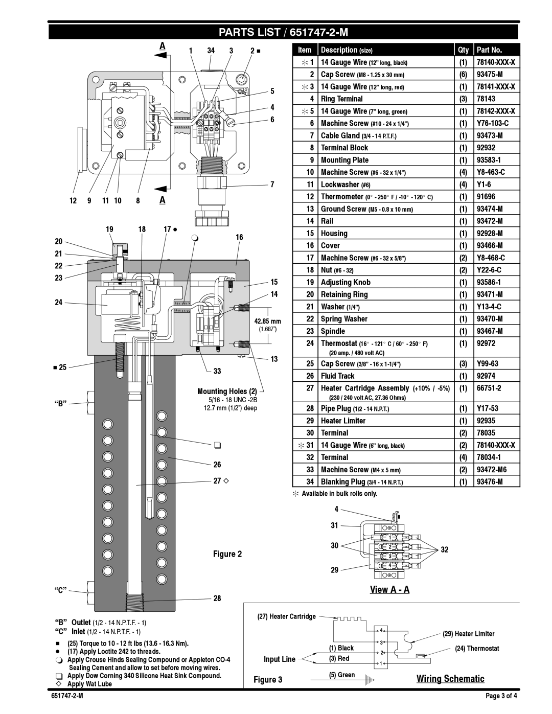
PARTS LIST / 651747-2-M
|
|
|
|
| A | 1 | 34 | 3 | 2 H |
|
|
|
|
|
| ||||
|
|
|
|
|
|
|
|
| 5 |
|
|
|
|
|
|
|
|
| 4 |
|
|
|
|
|
|
|
|
| 6 |
|
|
|
|
|
|
|
|
| 7 |
12 | 9 | 11 | 10 | 8 | A |
|
|
|
|
19 | 18 | 17 D | 16 |
20 |
| ` | |
|
|
| |
21 |
|
|
|
22 |
|
|
|
23 |
|
| 15 |
|
|
| |
24 |
|
| 14 |
|
|
| |
|
|
| 42.85 mm |
|
|
| (1.687”) |
H 25 |
|
| 13 |
|
| 33 | |
|
|
| |
|
| Mounting Holes (2) | |
“B” |
|
| 5/16 - 18 UNC |
|
| 12.7 mm (1/2”) deep | |
|
|
| |
![]() -
-
![]()
![]() 26
26 ![]() 27 Z
27 Z
Figure 2
“C” ![]()
![]() 28
28
Item | Description (size) | Qty | Part No. |
: 1 | 14 Gauge Wire (12” long, black) | (1) | |
2 | Cap Screw (M8 - 1.25 x 30 mm) | (6) | |
: 3 | 14 Gauge Wire (12” long, red) | (1) | |
4 | Ring Terminal | (3) | 78143 |
: 5 | 14 Gauge Wire (7” long, green) | (1) | |
6 | Machine Screw (#10 - 24 x 1/4”) | (1) | |
7 | Cable Gland (3/4 - 14 P.T.F.) | (1) | |
8 | Terminal Block | (1) | 92932 |
9 | Mounting Plate | (1) | |
10 | Machine Screw (#6 - 32 x 1/4”) | (4) | |
11 | Lockwasher (#6) | (4) | |
12 | Thermometer (0_ - 250_ F / | (1) | 91696 |
13 | Ground Screw (M5 - 0.8 x 10 mm) | (1) | |
14 | Rail | (1) | |
15 | Housing | (1) | |
16 | Cover | (1) | |
17 | Machine Screw (#6 - 32 x 5/8”) | (2) | |
18 | Nut (#6 - 32) | (2) | |
19 | Adjusting Knob | (1) | |
20 | Retaining Ring | (1) | |
21 | Washer (1/4”) | (1) | |
22 | Spring Washer | (1) | |
23 | Spindle | (1) | |
24 | Thermostat (16_ - 121_ C / 60_ - 250_ F) | (1) | 92972 |
| (20 amp. / 480 volt AC) |
|
|
25 | Cap Screw (3/8” - 16 x | (3) | |
26 | Fluid Track | (1) | 92974 |
27 | Heater Cartridge Assembly (+10% / | (1) | |
| (230 / 240 volt AC, 27.36 Ohms) |
|
|
28 | Pipe Plug (1/2 - 14 N.P.T.) | (1) | |
29 | Heater Limiter | (1) | 92935 |
30 | Terminal | (2) | 78035 |
: 31 | 14 Gauge Wire (6” long, black) | (2) | |
32 | Terminal | (4) | |
33 | Machine Screw (M4 x 5 mm) | (2) | |
34 | Blanking Plug (3/4 - 14 N.P.T.) | (1) |
:Available in bulk rolls only.
4
31
30 | 1 |
|
2 | 32 | |
| 3 | |
|
|
294
View A - A
“B” | Outlet (1/2 - 14 N.P.T.F. - 1) | (27) Heater Cartridge |
|
|
|
|
|
| (29) Heater Limiter | ||
“C” | Inlet (1/2 - 14 N.P.T.F. - 1) |
|
| 4 | |
|
|
|
|
| |
H (25) Torque to 10 - 12 ft lbs (13.6 - 16.3 Nm). |
| (1) Black | 3 | (24) Thermostat | |
D (17) Apply Loctite 242 to threads. |
| 2 | |||
Input Line | (3) Red |
| |||
` Apply Crouse Hinds Sealing Compound or Appleton | 1 |
| |||
| Sealing Cement and allow to set before moving wires. |
|
|
| |
|
| (5) Green |
|
| |
- Apply Dow Corning 340 Silicone Heat Sink Compound. | Figure 3 |
| Wiring Schematic | ||
Z Apply Wat Lube |
|
| |||
|
|
|
| ||
|
|
| Page 3 of 4 | ||