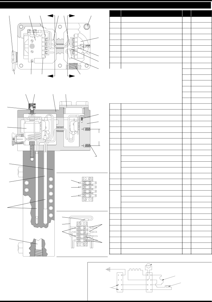
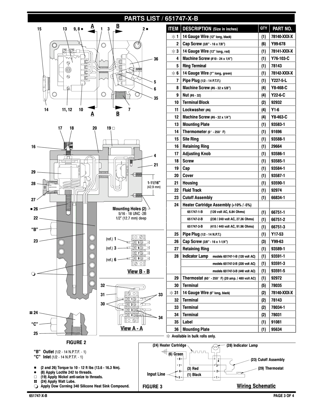
651747-X-B specifications
The Ingersoll-Rand 651747-X-B is a robust and highly efficient air compressor designed for various industrial applications. Known for its reliability and performance, this model stands out due to its advanced technologies and user-friendly features.One of the key features of the Ingersoll-Rand 651747-X-B is its powerful, electric-driven compressor system. This ensures consistent airflow and pressure, making it ideal for demanding tasks in construction, automotive, and manufacturing sectors. The compressor is engineered to deliver optimal performance while minimizing energy consumption, which not only reduces operating costs but also enhances sustainability.
The 651747-X-B is equipped with a durable and high-quality construction that withstands the rigors of everyday use. Its heavy-duty components are designed to endure tough working conditions, providing extended service life and reducing the frequency of maintenance needs. This model's robust design is complemented by an efficient cooling system, which prevents overheating and ensures the compressor operates at peak efficiency.
Another notable characteristic of the Ingersoll-Rand 651747-X-B is its advanced control technology. The compressor features a user-friendly interface that allows operators to easily monitor and adjust settings in real time, promoting operational efficiency and safety. This technology enables automatic start-stop operations, which further conserves energy and enhances user convenience.
Moreover, the 651747-X-B incorporates noise-reducing technologies to operate quietly, making it suitable for environments where noise levels need to be kept to a minimum. The sound insulation features help create a more pleasant work atmosphere while complying with regulatory noise standards.
Maintenance is simplified with the Ingersoll-Rand 651747-X-B. Its design includes easy access to key components, making routine checks and servicing straightforward. This feature is vital for businesses aiming to minimize downtime and maximize productivity.
In summary, the Ingersoll-Rand 651747-X-B is a highly efficient air compressor that combines durability, performance, and user-friendly technology. With its robust construction, advanced control systems, energy-efficient operations, and lower noise levels, it is an excellent choice for various demanding industrial applications, ensuring reliability and integrity in every operation.

