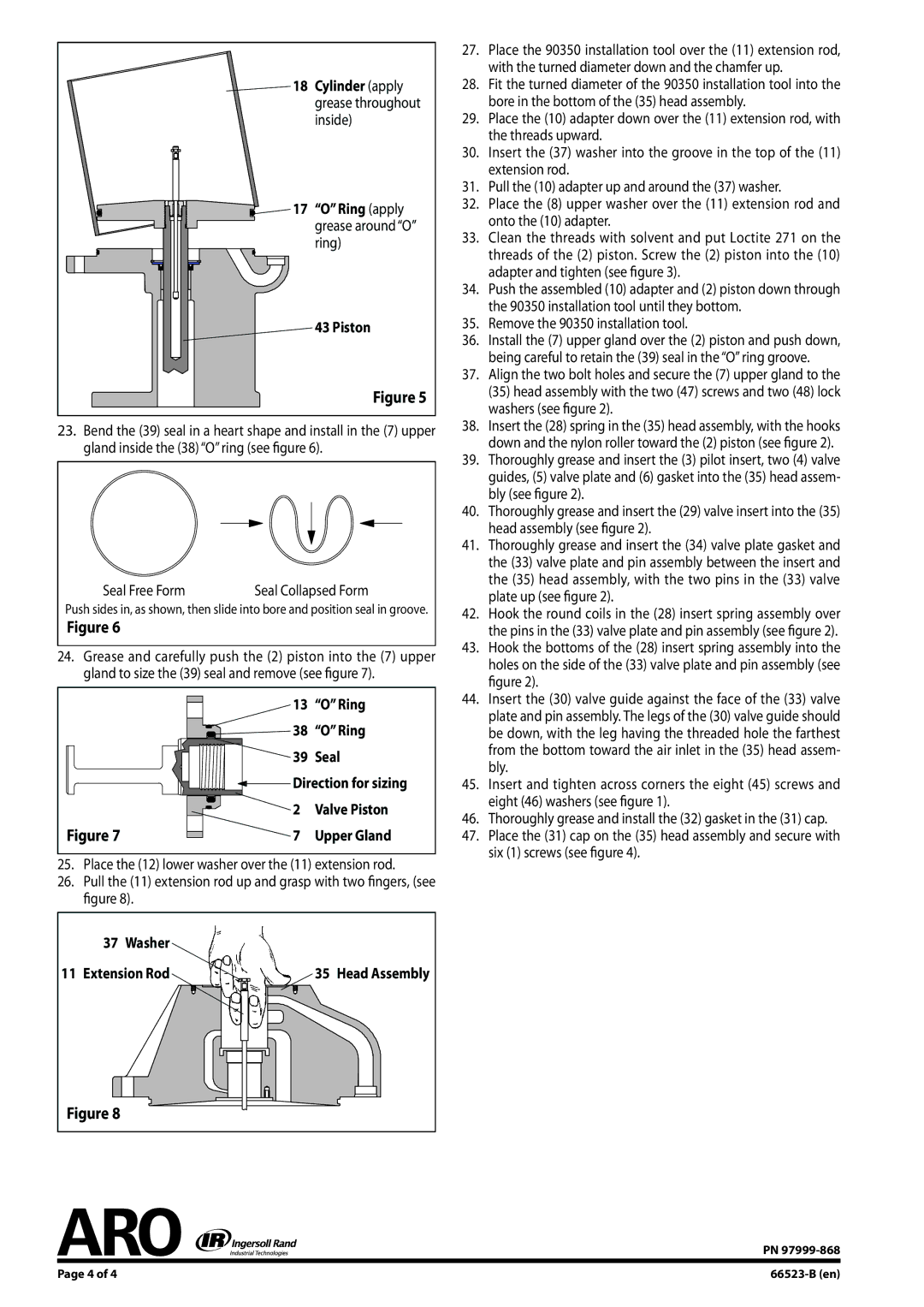
18 Cylinder (apply grease throughout inside)

17 “O” Ring (apply grease around “O” ring)

43 Piston

Figure 5

23.Bend the (39) seal in a heart shape and install in the (7) upper gland inside the (38) “O” ring (see figure 6).

Seal Free Form

Seal Collapsed Form

Push sides in, as shown, then slide into bore and position seal in groove.

Figure 6

24.Grease and carefully push the (2) piston into the (7) upper gland to size the (39) seal and remove (see figure 7).


13

“O” Ring


38

“O” Ring


39

Seal


Direction for sizing


2

Valve Piston

Figure 7

7

Upper Gland

25.Place the (12) lower washer over the (11) extension rod.

26.Pull the (11) extension rod up and grasp with two fingers, (see figure 8).

37 Washer

11 Extension Rod

35 Head Assembly

Figure 8

27.Place the 90350 installation tool over the (11) extension rod, with the turned diameter down and the chamfer up.

28.Fit the turned diameter of the 90350 installation tool into the bore in the bottom of the (35) head assembly.

29.Place the (10) adapter down over the (11) extension rod, with the threads upward.

30.Insert the (37) washer into the groove in the top of the (11) extension rod.

31.Pull the (10) adapter up and around the (37) washer.

32.Place the (8) upper washer over the (11) extension rod and onto the (10) adapter.

33.Clean the threads with solvent and put Loctite 271 on the threads of the (2) piston. Screw the (2) piston into the (10) adapter and tighten (see figure 3).

34.Push the assembled (10) adapter and (2) piston down through the 90350 installation tool until they bottom.

35.Remove the 90350 installation tool.

36.Install the (7) upper gland over the (2) piston and push down, being careful to retain the (39) seal in the “O” ring groove.

37.Align the two bolt holes and secure the (7) upper gland to the (35) head assembly with the two (47) screws and two (48) lock washers (see figure 2).

38.Insert the (28) spring in the (35) head assembly, with the hooks down and the nylon roller toward the (2) piston (see figure 2).

39.Thoroughly grease and insert the (3) pilot insert, two (4) valve guides, (5) valve plate and (6) gasket into the (35) head assem- bly (see figure 2).

40.Thoroughly grease and insert the (29) valve insert into the (35) head assembly (see figure 2).

41.Thoroughly grease and insert the (34) valve plate gasket and the (33) valve plate and pin assembly between the insert and the (35) head assembly, with the two pins in the (33) valve plate up (see figure 2).

42.Hook the round coils in the (28) insert spring assembly over the pins in the (33) valve plate and pin assembly (see figure 2).

43.Hook the bottoms of the (28) insert spring assembly into the holes on the side of the (33) valve plate and pin assembly (see figure 2).

44.Insert the (30) valve guide against the face of the (33) valve plate and pin assembly. The legs of the (30) valve guide should be down, with the leg having the threaded hole the farthest from the bottom toward the air inlet in the (35) head assem- bly.

45.Insert and tighten across corners the eight (45) screws and eight (46) washers (see figure 1).

46.Thoroughly grease and install the (32) gasket in the (31) cap.

47.Place the (31) cap on the (35) head assembly and secure with six (1) screws (see figure 4).


PN 97999-868


Page of 4

66523-B (en)

Page 4
Image 4
Ingersoll-Rand 66523-B manual Ring apply grease around O ring Piston, Washer Extension Rod

66523-B specifications

The Ingersoll-Rand 66523-B is a robust air compressor that stands out in the world of industrial equipment due to its reliability, efficiency, and advanced technology. Designed for a variety of applications, this compressor is particularly favored in sectors that require consistent air supply for pneumatic tools, powering equipment, and general maintenance tasks.

One of the main features of the Ingersoll-Rand 66523-B is its significant air delivery capacity, which typically ranges from 5 to 15 CFM at 90 PSI. This capability makes it suitable for both light and heavy-duty applications, allowing users to run multiple tools simultaneously without loss of pressure. The compressor’s efficient motor provides a reliable performance, ensuring that tasks are completed without interruptions.

The construction of the Ingersoll-Rand 66523-B focuses on durability, featuring high-quality materials that resist wear and tear over extended use. Coupled with a compact design, it can fit into various working environments without taking up excessive space. This makes it an ideal choice for workshops, garages, and small manufacturing plants.

One of the key technologies embedded in the Ingersoll-Rand 66523-B is its advanced cooling system. This system prevents overheating during prolonged operation, thereby extending the lifespan of the compressor. The compressor is also equipped with a pressure switch that automatically turns the unit off when it reaches the desired pressure level, contributing to energy savings and reducing wear on components.

Moreover, the Ingersoll-Rand 66523-B features a user-friendly interface, enabling easy operation even for novice users. Maintenance is straightforward, thanks to the accessibility of key components, which simplifies tasks like oil changes or filter replacements.

In terms of noise levels, the Ingersoll-Rand 66523-B operates at a relatively low decibel range, making it a more pleasant option for work environments where noise is a concern. This feature enhances comfort and promotes a productive working atmosphere.

Overall, the Ingersoll-Rand 66523-B is a versatile and reliable air compressor, equipped with technologies that promote efficiency, durability, and user-friendliness. Its combination of performance, design, and ease of maintenance makes it a favored choice among professionals who demand top performance from their tools. Whether for automotive work, manufacturing, or DIY projects, this compressor delivers exceptional performance and reliability.