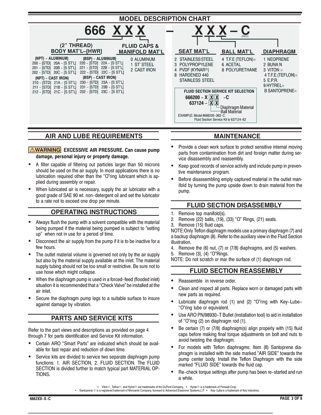
MODEL DESCRIPTION CHART

666 X X X

(2'' THREAD)

FLUID CAPS &

BODY MAT'L±[HWR]

MANIFOLD MAT'L

(NPT) - ALUMINUM)

(BSP) - ALUMINUM)


￿ ￿LUMINUM

2￿￿ ￿ [ST￿] 2￿￿ ￿ [S ST'L]

22￿ ￿ [ST￿] 22￿ ￿ [S ST'L]

￿ ST' ST￿￿L

2￿￿ ￿ [ST￿] 2￿￿ ￿ [S ST'L]

22￿ ￿ [ST￿] 22￿ ￿ [S ST'L]

2 ￿￿ST IRON

2￿2 ￿ [ST￿] 2￿￿ ￿ [S ST'L]

222 ￿ [ST￿] 22￿ ￿ [S ST'L]


(NPT) - CAST IRON)

(BSP) - CAST IRON)


2￿￿ ￿ [ST￿] 2￿￿ ￿ [S ST'L]

2￿￿ ￿ [ST￿] 2￿￿ ￿ [S ST'L]


2￿￿ ￿ [ST￿] 2￿￿ ￿ [S ST'L]

2￿￿ ￿ [ST￿] 2￿￿ ￿ [S ST'L]


2￿2 ￿ [ST￿] 2￿￿ ￿ [S ST'L]

2￿2 ￿ [ST￿] 2￿￿ ￿ [S ST'L]


±X X X ± C

(REV)


SEAT MAT'L

BALL MAT'L

DIAPHRAGM

2

ST￿INL￿SS ST￿￿L

￿ T.￿.￿ (T￿￿LON)R

￿ N￿OPR￿N￿

￿ POLYPROPYL￿N￿

￿ ￿￿￿T￿L

2 ￿UN￿ N

￿

PV￿￿ (KYN￿Rr)

￿ POLYUR￿TH￿N￿

￿ VITON R

￿

H￿R￿￿N￿￿ ￿￿￿


￿ T.￿.￿.(T￿￿LON)R


ST￿INL￿SS ST￿￿L


￿ ￿.P.R.


￿ HYTR￿LR


FLUID SECTION SERVICE KIT SELECTION


￿ S￿NTOPR￿N￿R


666200 - X X X

-C


637124 - X X

￿iaphragm Material


￿all Material


￿X￿MPL￿: Model #￿￿￿2￿￿￿￿￿2￿￿


￿luid Section Service Kit is ￿￿￿￿2￿￿￿2


AIR AND LUBE REQUIREMENTS


MAINTENANCE

WARNING EXCESSIVE AIR PRESSURE. Can cause pump damage, personal injury or property damage.

S￿ filter capable of filtering out particles larger than ￿￿ microns should be used on the air supply. In most applications there is no lubrication required other than the ``O￿ring lubricant which is apH plied during assembly or repair.

SWhen lubricated air is necessary￿ supply the air lubricator with a good grade of S￿￿ ￿￿ wt. non￿detergent oil and set the lubricator to a rate not to exceed one drop per minute.

OPERATING INSTRUCTIONS

S￿lways flush the pump with a solvent compatible with the material being pumped if the material being pumped is subject to ￿setting up￿ when not in use for a period of time.

S￿isconnect the air supply from the pump if it is to be inactive for a few hours.

SThe outlet material volume is governed not only by the air supply but also by the material supply available at the inlet. The material supply tubing should not be too small or restrictive. ￿e sure not to use hose which might collapse.

SWhen the diaphragm pump is used in a forced￿feed (flooded inlet) situation it is recommended that a ``￿heck Valve￿ be installed at the air inlet.

SSecure the diaphragm pump legs to a suitable surface to insure against damage by vibration.

PARTS AND SERVICE KITS

Refer to the part views and descriptions as provided on page ￿ through ￿ for parts identification and Service Kit information.

S￿ertain ￿RO ``Smart Parts￿ are indicated which should be availH able for fast repair and reduction of down time.

SService kits are divided to service two separate diaphragm pump functions: ￿. ￿IR S￿￿TION￿ 2. ￿LUI￿ S￿￿TION. The ￿LUI￿ S￿￿TION is divided further to match typical part M￿T￿RI￿L OPH TIONS.

SProvide a clean work surface to protect sensitive internal moving parts from contamination from dirt and foreign matter during serH vice disassembly and reassembly.

SKeep good records of service activity and include pump in prevenH tive maintenance program.

S￿efore disassembling empty captured material in the outlet manH ifold by turning the pump upside down to drain material from the pump.

FLUID SECTION DISASSEMBLY

￿. Remove top manifold(s).

2.Remove (22) balls￿ (￿￿)￿ (￿￿) ``O￿ Rings￿ (2￿) seats. ￿. Remove (￿￿) fluid caps.

NOT￿:Only Teflon diaphragm models use a primary diaphragm (￿) and a backup diaphragm (￿). Refer to the auxiliary view in the ￿luid Section illustration.

￿. Remove the (￿) nut￿ (￿) or (￿/￿) diaphragms￿ and (￿) washers. ￿. Remove (￿)￿ (￿) ``O￿Rings.

NOT￿: ￿o not scratch or mar the surface of (￿) diaphragm rod.

FLUID SECTION REASSEMBLY

SReassemble in reverse order.

S￿lean and inspect all parts. Replace worn or damaged parts with new parts as required.

SLubricate diaphragm rod (￿) and (2) ``O￿ring with Key￿LubeR ``O￿ring lube or equivalent.

SUse ￿RO PN/￿￿￿￿￿￿T ￿ullet (installation tool) to aid in installation of ``O￿ring (2) on diaphragm rod (￿).

S￿e certain (￿) or (￿/￿) diaphragm(s) align properly with (￿￿) fluid caps before making final torque adjustments on bolt and nuts to avoid twisting the diaphragm.

S￿or models with Teflon diaphragms: Item (￿) Santoprene diaH phragm is installed with the side marked ￿￿IR SI￿￿￿ towards the pump center body. Install the Teflon ￿iaphragm with the side marked ￿￿LUI￿ SI￿￿￿ towards the fluid cap.

SRe￿check torque settings after pump has been re￿started and run a while.

S VitonR￿ TeflonR￿ and HytrelR are trademarks of the ￿uPont ￿ompany￿ S KynarR is a trademark of Penwalt ￿orp￿

S Santoprene R is a registered trademark of Monsanto ￿ompany￿ licensed to ￿dvanced ￿lastomer Systems￿L.P. S Key￿Lube is a trademark of Key Industries.

6662XX-X-C

PAGE￿￿3 OF 8

Page 3
Image 3
Ingersoll-Rand 6662XX-X-C manual 666 X X, ± X X X ± C

6662XX-X-C specifications

The Ingersoll-Rand 6662XX-X-C is a powerful and versatile air compressor designed to meet the demanding needs of various industrial applications. Renowned for its durability and efficiency, this model is a testament to Ingersoll-Rand's legacy of engineering excellence.

One of the standout features of the 6662XX-X-C is its robust construction. Built with high-quality materials, the compressor is designed to withstand harsh operating conditions, ensuring long-term reliability. This makes it suitable for industries such as construction, manufacturing, and automotive, where durability is paramount.

The 6662XX-X-C is equipped with a highly efficient rotary screw compressor mechanism. This technology allows for continuous airflow, making it an excellent choice for applications requiring constant pneumatic power. With its advanced engineering, the compressor reduces energy consumption while maximizing output, resulting in lower operational costs for users.

Another notable characteristic of this model is its quiet operation. Utilizing soundproofing technology, the Ingersoll-Rand 6662XX-X-C minimizes noise levels, creating a more pleasant work environment. This feature is particularly beneficial in settings where noise regulations are stringent or in indoor applications where excessive sound can be disruptive.

The compressor also boasts an easy-to-use digital control panel that allows operators to monitor and adjust settings effortlessly. This user-friendly interface provides real-time data, including pressure levels and performance metrics, enabling users to maintain optimal operating conditions.

In terms of maintenance, the 6662XX-X-C is designed with accessibility in mind. Key components are easily reachable, allowing for quick routine checks and servicing. This design effectively reduces downtime and ensures that the compressor operates at peak efficiency.

The Ingersoll-Rand 6662XX-X-C is also highly adaptable. It can be fitted with a range of accessories and attachments, including dryers and filters, allowing customization to suit specific industrial needs. This versatility makes it an invaluable asset in various applications, from powering pneumatic tools to supplying air for industrial automation systems.

With its combination of durability, efficiency, and user-friendly features, the Ingersoll-Rand 6662XX-X-C stands out as a reliable choice for those in need of a versatile air compressor that delivers consistent performance under pressure. Whether in a bustling construction site or a quiet workshop, this model is engineered to meet the challenges of modern industrial demands.