2b | 4 | 3 | 2a | 1 |
MODEL 7980–A–( )
5
8 | 7 | 6 |
MODEL
17 | 16 | 15 | 14 |
9
10
MODEL
11
12
13
DISASSEMBLY/ASSEMBLY INSTRUCTIONS
NOTICE
•
•
•
•
•
•
_
_
_
_
•
•
_
_
_
Never apply excessive pressure by a holding device which may cause distortion of a part.
Apply pressure evenly to parts which have a press fit. Apply even pressure to the bearing race that will be press fitted to the mating part.
Use correct tools and fixtures when servicing this tool. Don’t damage ‘‘O” rings when servicing this tool.
Use only genuine ARO replacement parts for this tool. When ordering, specify part number, description, tool model number and serial number.
DISASSEMBLY
Remove hose assembly (not shown) from the inlet of the tool. Insert A 1/8” diameter pin thru the hole in the housing (26), lock sleeve (29) and spindle (28).
Using a wrench on flats of housing cap (32), unthread and re- move housing cap (32) and lock sleeve (29).
Using a wrench on flats of nosepiece (34), unthread and re- move from spindle, releasing collet (33).
Models 7980–2–( ) – Place head (7) in a vise and, using a strap type wrench, unthread and remove housing (26). Models 7980–A–( ) – Clamp wrench (30131) flatwise in a vise and place slot in air inlet of tool on wrench. Using a strap type wrench, unthread and remove housing (26).
Remove nozzle plate (18).
Insert a 1/8” diameter pin thru the hole in housing (26) and spindle (28), and remove nut (19).
Press spindle (28) out nose end of housing.
_
_
•
•
_
_
_
_
_
_
_
_
•
Remove impellers (21, 22 and 24), sleeve (20), bearing (23) and spacer (25) from housing.
Do not remove bearing (27) from spindle unless damage is ev- ident. To remove, press off of spindle.
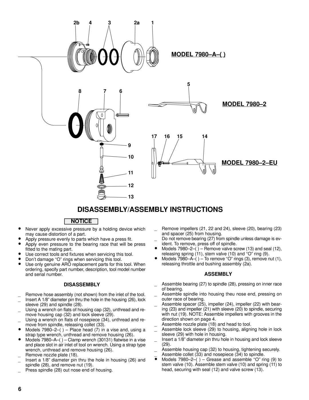
Models 7980–2–( ) – Remove valve screw (13) and seal (12), releasing spring (11), stem valve (10) and ‘‘O” ring (9). Models 7980–A–( ) – To remove ‘‘O” rings (3), remove nut (1), releasing throttle and bushing assembly (2a).
ASSEMBLY
Assemble bearing (27) to spindle (28), pressing on inner race of bearing.
Assemble spindle into housing theu nose end, pressing on outer race of bearing.
Assemble spacer (25), impeller (24), impeller (22) with bear- ing (23) and impeller (21) with sleeve (20) to spindle, securing with nut (19). NOTE: Assemble impellers with grooves in the direction shown on page 4.
Assemble nozzle plate (18) and head to tool.
Assemble lock sleeve (29) to housing, aligning hole in lock sleeve (29) with hole in housing.
Insert a 1/8” diameter pin thru hole in housing and lock sleeve (29).
Assemble housing cap (32) to housing, tightening securely. Assemble collet (33) and nosepiece (34) to spindle.
Models 7980–2–( ) – Grease and assemble ‘‘O” ring (9) to stem valve (10). Assemble stem valve (10) and spring (11) to head, securing with seal (12) and valve screw (13).
6
