M104 | |
HYDRAULICCHECK | 13 |
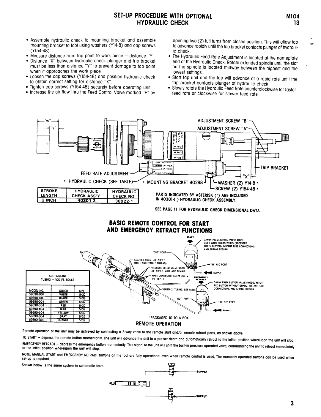
Assemble hydraulic check to mounting bracket and assemble mounting bracket to tool using washers
Measure distance from tap point to work piece - distance “Y”. Distance “X”between hydraulic check plunger and trip bracket must be less than distance “Y”to prevent damage to tap point when it approaches the work piece.
Loosenthe cap screws
Tighten cap screws
Y
l
l
l
opening two (2) full turns from closed position, This will allow tap to advancerapidly until the trip bracketcontactsplungerof hydraul- ic check.
The Hydraulic FeedRateAdjustment is located at the nameplate end of the Hydraulic Check.Rotateextendedspindle until the slot on the spindle is located midway between the highest and the lowest settings.
Start tap unit and the tap will advance at a rapid rate until the trip bracket contacts plunger of hydraulic check,
Slowly rotatethe Hydraulic FeedRatecounterclockwisefor faster feed rate or clockwise for slower feed rate.
ADJUSTMENTSCREW
BASIC REMOTECONTROLFORSTART
AND EMERGENCYRETRACTFUNCTIONS
“OUT” PORT
RED BUTTON WITHOUT GUARD. INSTANT TUBE CONNECTIONS AND SPRING RETURN
. PACKAGED10 TOA BOX
REMOTE OPERATION
Remoteoperation of the unit may be achieved by connecting
TOSTART- depress the remote button momentarily. The unit will advance the drill to a preset depth and automatically retract to the initial position whereupon the unit will stop.
EMERGENCYRETRACT- depressthe emergency button momentarily.Thissignal to the unit will shift the
NOTE:MANUALSTARTand EMERGENCYRETRACTbuttons on the tool are fully operational even when remote control is used, The manually operated buttons can be used when
Shown below is the some system in schematic form.
