MODEL IDENTIFICATION
FE 07 4 B– XX X –A
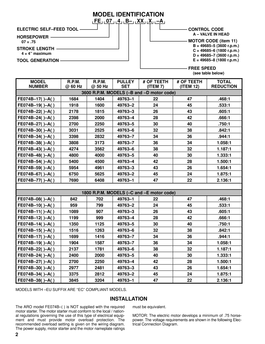
ELECTRIC ![]()
HORSEPOWER
07 = .75
STROKE LENGTH
4 = 4” maximum
TOOL GENERATION
 CONTROL CODE
A – VALVE IN HEAD
MOTOR CODE (item 11)
B =
C =
D =
E =
FREE SPEED
(see table below)
MODEL | R.P.M. | R.P.M. | PULLEY | # OF TEETH |
| # OF TEETH | TOTAL |
NUMBER | @ 60 Hz | @ 50 Hz | SET | (ITEM 7) |
| (ITEM 12) | REDUCTION |
| 3600 R.P.M. MODELS |
|
| ||||
FE074B–17( )–A( ) | 1684 | 1404 | 22 |
| 47 | .468:1 | |
FE074B–19( )–A( ) | 1918 | 1600 | 24 |
| 45 | .533:1 | |
FE074B–22( )–A( ) | 2178 | 1815 | 26 |
| 43 | .605:1 | |
FE074B–24( )–A( ) | 2398 | 2000 | 28 |
| 42 | .666:1 | |
FE074B–27( )–A( ) | 2700 | 2250 | 30 |
| 40 | .750:1 | |
FE074B–30( )–A( ) | 3031 | 2525 | 32 |
| 38 | .842:1 | |
FE074B–34( )–A( ) | 3398 | 2832 | 34 |
| 36 | .944:1 | |
FE074B–38( )–A( ) | 3808 | 3173 | 36 |
| 34 | 1.058:1 | |
FE074B–43( )–A( ) | 4274 | 3562 | 38 |
| 32 | 1.187:1 | |
FE074B–48( )–A( ) | 4800 | 4000 | 40 |
| 30 | 1.333:1 | |
FE074B–54( )–A( ) | 5400 | 4500 | 42 |
| 28 | 1.500:1 | |
FE074B–59( )–A( ) | 5954 | 4961 | 43 |
| 26 | 1.654:1 | |
FE074B–67( )–A( ) | 6750 | 5625 | 45 |
| 24 | 1.875:1 | |
FE074B–77( )–A( ) | 7690 | 6408 | 47 |
| 22 | 2.136:1 | |
|
|
|
|
|
|
|
|
| 1800 R.P.M. MODELS |
|
| ||||
FE074B–08( )–A( ) | 842 | 702 | 22 |
| 47 | .468:1 | |
FE074B–10( )–A( ) | 959 | 799 | 24 |
| 45 | .533:1 | |
FE074B–11( )–A( ) | 1089 | 907 | 26 |
| 43 | .605:1 | |
FE074B–12( )–A( ) | 1199 | 999 | 28 |
| 42 | .666:1 | |
FE074B–14( )–A( ) | 1350 | 1125 | 30 |
| 40 | .750:1 | |
FE074B–15( )–A( ) | 1516 | 1263 | 32 |
| 38 | .842:1 | |
FE074B–17( )–A( ) | 1699 | 1416 | 34 |
| 36 | .944:1 | |
FE074B–19( )–A( ) | 1904 | 1587 | 36 |
| 34 | 1.058:1 | |
FE074B–22( )–A( ) | 2137 | 1781 | 38 |
| 32 | 1.187:1 | |
FE074B–24( )–A( ) | 2400 | 2000 | 40 |
| 30 | 1.333:1 | |
FE074B–27( )–A( ) | 2700 | 2250 | 42 |
| 28 | 1.500:1 | |
FE074B–30( )–A( ) | 2977 | 2481 | 43 |
| 26 | 1.654:1 | |
FE074B–34( )–A( ) | 3375 | 2812 | 45 |
| 24 | 1.875:1 | |
FE074B–38( )–A( ) | 3845 | 3204 | 47 |
| 22 | 2.136:1 | |
MODELS WITH
INSTALLATION
The ARO model FE074B–( ) is NOT supplied with the required motor starter. The motor starter must conform to the local / nation- al regulations governing the use of this type of electrical equip- ment and must provide motor overload protection. The recommended overload setting is given on the wiring diagram. The power supply, motor starter and the motor nameplate ratings
must be equivalent.
MOTOR: The electric motor develops a minimum of .75 horse- power. The voltage requirements are shown in the following Elec- trical Connection Diagram.
2