TROUBLE SHOOTING
Product discharged from exhaust outlet.
SCheck for diaphragm rupture.
SCheck tightness of (14) diaphragm screw.
Air bubbles in product discharge.
SCheck connections of suction plumbing.
SCheck “O” rings between intake manifold and inlet side fluid caps.
SCheck tightness of (14) diaphragm screw.
Motor blows air or stalls.
SCheck (176) check valve for damage or wear.
SCheck for restrictions in valve / exhaust.
Low output volume, erratic flow, or no flow.
SCheck air supply.
SCheck for plugged outlet hose.
SCheck for kinked (restrictive) outlet material hose.
SCheck for kinked (restrictive) or collapsed inlet material hose.
SCheck for pump cavitation
SCheck all joints on the inlet manifolds and suction connections. These must be air tight.
SInspect the pump for solid objects logged in the diaphragm chamber or the seat area.
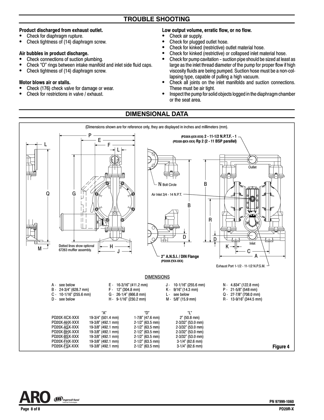
DIMENSIONAL DATA
(Dimensions shown are for reference only, they are displayed in inches and millimeters (mm).
P | |
E | |
L | F |
![]() L
L ![]()
Outlet
N Bolt Circle | B |
Q | G | Air Inlet 3/4 - 14 N.P.T. |
B
R
M | Dotted lines show optional |
67263 muffler assembly. |
D | D |
H | Inlet |
K | |
J | C |
2” A.N.S.I. / DIN Flange | A |
| |
| Exhaust Port |
DIMENSIONS
A - | see below | E - | J - | N - | 4.834” (122.8 mm) | ||
B - | F - | 12” (304.8 mm) | K - | 9/16” (14.3 mm) | P - | ||
C - | G - | L - | see below | Q - | |||
D - | see below | H - | M - | 5/8” (15.9 mm) | R - |
| “A” | “D” | “L” |
|
2” (50.8 mm) |
| |||
| ||||
| ||||
| ||||
| ||||
Figure 4 | ||||
PN
Page 8 of 8 |
