PARTS LIST | Need Help? Call 800-573-2860 |
LISTE DES PIÈCES | Besoin d’assistance ? Appeler le 800-573-2860 |
LISTA DE PIEZAS | ¿Necesita ayuda? Llame al 800-573-2860 |
|
ANT-TVM103 - 13-30”Swivel /33 à 76,2 cm (13 à 30 po) pivotant / Spanish (1)
BM4 x 10mm Screw / Vis M4 x 10 mm / Spanish (4)
C1/4 x 2 ¾ in. Truss Head Lag Bolt / Vis à bois à tête bombée de 1/4 x 2 ¾ po / Spanish (2)
D3/16 in. Allen Wrench / Clé hexagonale de 4,76 mm (3/16 po) / Spanish (1)
E5/32 in. Allen Wrench / Clé hexagonale de 3,97 mm (5/32 po) / Spanish (1)
FBubble Level /Niveau à bulle / Spanish (1)
3 | Place the bubble level (F) on top of the bracket and adjust the bracket until |
the bubble is centered. Mark the location of the bottom hole and drill |
the hole.
Placer le niveau à bulle (F) sur le dessus du support et bouger | F | F |
celui-ci jusqu’à ce que la bulle du niveau soit centrée. |
Marquer l’emplacement du trou inférieur et le percer. | | |
Coloque el nivel de burbuja (F) en la parte superior del soporte y ajuste el soporte hasta que la burbuja sea centrada. Marque el lugar del agujero inferior y taladre el agujero.
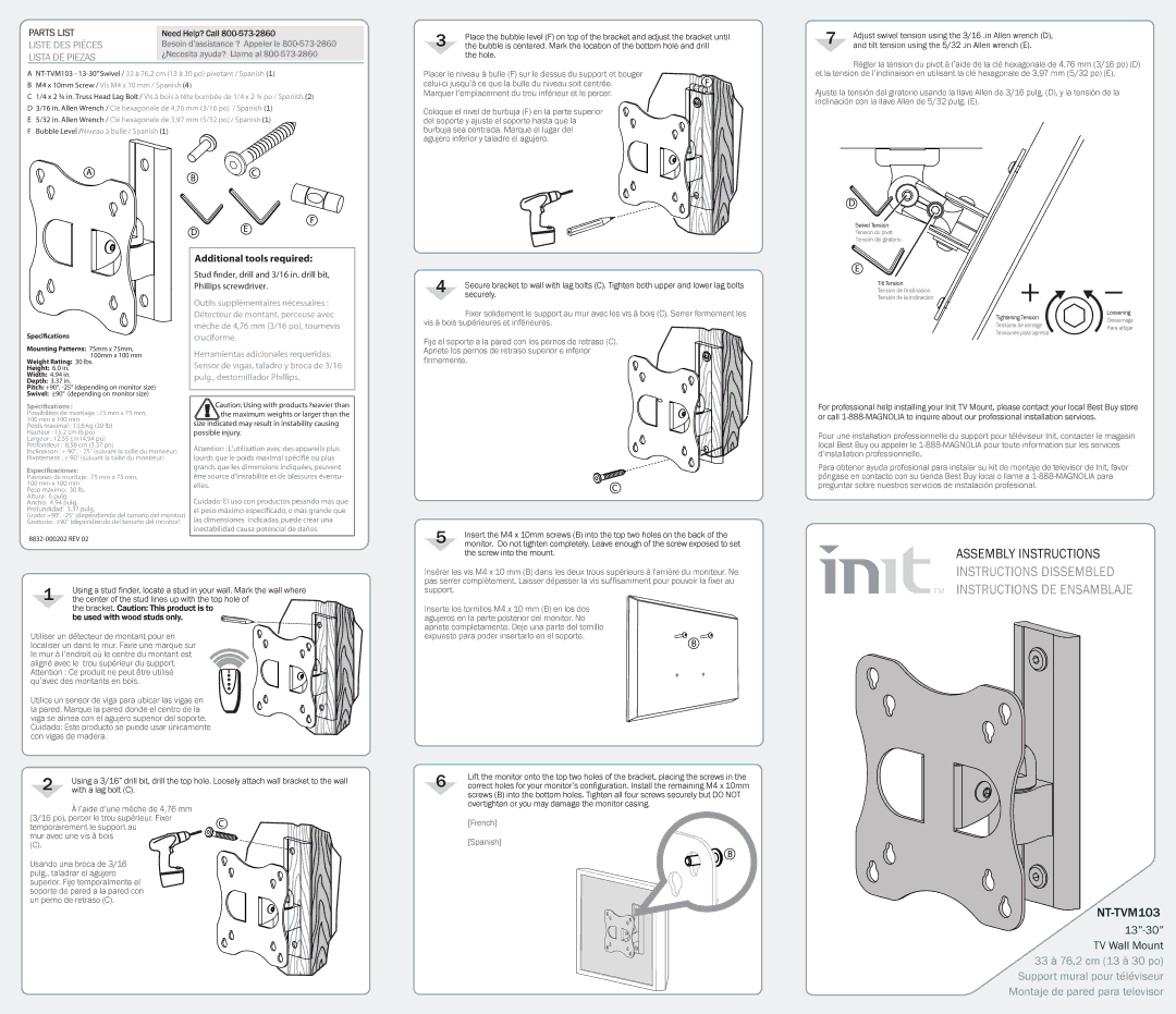
7 | Adjust swivel tension using the | 3/16 .in Allen wrench (D), |
and tilt tension using the 5/32 | .in Allen wrench (E). |
Régler la tension du pivot à l’aide de la clé hexagonale de 4,76 mm (3/16 po) (D) et la tension de l’inclinaison en utilisant la clé hexagonale de 3,97 mm (5/32 po) (E).
Ajuste la tensión del giratorio usando la llave Allen de 3/16 pulg. (D), y la tensión de la inclinación con la llave Allen de 5/32 pulg. (E).
Specications
Mounting Patterns: 75mm x 75mm,
100mm x 100 mm
Weight Rating: 30 lbs.
Height: 6.0 in.
Width: 4.94 in.
Depth: 3.37 in.
Pitch: +90°, -25° (depending on monitor size)
Swivel: ±90° (depending on monitor size)
Spécications :
Possibilités de montage : 75 mm x 75 mm, 100 mm x 100 mm
Poids maximal : 13,6 kg (30 lb)
Hauteur : 15,2 cm (6 po)
Largeur : 12,55 cm (4,94 po)
Profondeur : 8,56 cm (3,37 po)
Inclinaison : + 90°, - 25° (suivant la taille du moniteur)
Pivotement : ± 90° (suivant la taille du moniteur)
Especicaciones:
Patrones de montaje: 75 mm x 75 mm, 100 mm x 100 mm
Peso máximo: 30 lb.
Altura: 6 pulg.
Ancho: 4.94 pulg.
Profundidad: 3.37 pulg.
Grado: +90°, -25° (dependiendo del tamaño del monitor)
Giratorio: ±90° (dependiendo del tamaño del monitor)
8832-000202 REV 02
Additional tools required:
Stud nder, drill and 3/16 in. drill bit, Phillips screwdriver.
Outils supplémentaires nécessaires : Détecteur de montant, perceuse avec mèche de 4,76 mm (3/16 po), tournevis cruciforme.
Herramientas adicionales requeridas: Sensor de vigas, taladro y broca de 3/16 pulg., destornillador Phillips.
!Caution: Using with products heavier than the maximum weights or larger than the
size indicated may result in instability causing possible injury.
Attention : L’utilisation avec des appareils plus lourds que le poids maximal spécifié ou plus grands que les dimensions indiquées, peuvent être source d’instabilité et de blessures éventu- elles.
Cuidado: El uso con productos pesando más que el peso máximo especificado, o más grande que las dimensiones indicadas, puede crear una inestabilidad causa potencial de daños.
4 | Secure bracket to wall with lag bolts (C). Tighten both upper and lower lag bolts |
securely. |
Fixer solidement le support au mur avec les vis à bois (C). Serrer fermement les vis à bois supérieures et inférieures.
Fije el soporte a la pared con los pernos de retraso (C). Apriete los pernos de retraso superior e inferior firmemente.
C
5 | Insert the M4 x 10mm screws (B) into the top two holes on the back of the |
monitor. Do not tighten completely. Leave enough of the screw exposed to set |
the screw into the mount.
E
Tilt Tension
Tension de l’inclinaison
Tensión de la inclinación
| Tightening Tension | Loosening |
| Desserrage |
| Tensions de serrage |
| Para aflojar |
| Tensiones para apretar |
| |
For professional help installing your Init TV Mount, please contact your local Best Buy store or call 1-888-MAGNOLIA to inquire about our professional installation services.
Pour une installation professionnelle du support pour téléviseur Init, contacter le magasin local Best Buy ou appeler le 1-888-MAGNOLIA pour toute information sur les services d’installation professionnelle.
Para obtener ayuda profesional para instalar su kit de montaje de televisor de Init, favor póngase en contacto con su tienda Best Buy local o llame a 1-888-MAGNOLIA para preguntar sobre nuestros servicios de instalación profesional.
ASSEMBLY INSTRUCTIONS
1 | Using a stud finder, locate a stud in your wall. Mark the wall where | |
the center of the stud lines up with the top hole of | F |
| the bracket. Caution: This product is to |
| be used with wood studs only. | |
Utiliser un détecteur de montant pour en localiser un dans le mur. Faire une marque sur le mur à l’endroit où le centre du montant est aligné avec le trou supérieur du support. Attention : Ce produit ne peut être utilisé qu’avec des montants en bois.
Utilice un sensor de viga para ubicar las vigas en la pared. Marque la pared donde el centro de la viga se alinea con el agujero superior del soporte. Cuidado: Este producto se puede usar únicamente con vigas de madera.
2 | Using a 3/16” drill bit, drill the top hole. Loosely attach wall bracket to the wall |
with a lag bolt (C). |
À l’aide d’une mèche de 4,76 mm
| (3/16 po), percer le trou supérieur. Fixer | C | |
| temporairement le support au | F |
| |
| mur avec une vis à bois | |
| | |
| (C). | | |
Usando una broca de 3/16 pulg., taladrar el agujero superior. Fije temporalmente el soporte de pared a la pared con un perno de retraso (C).
Insérer les vis M4 x 10 mm (B) dans les deux trous supérieurs à l'arrière du moniteur. Ne pas serrer complètement. Laisser dépasser la vis suffisamment pour pouvoir la fixer au support.
Inserte los tornillos M4 x 10 mm (B) en los dos agujeros en la parte posterior del monitor. No apriete completamente. Deje una parte del tornillo expuesto para poder insertarlo en el soporte.
B
6 | Lift the monitor onto the top two holes of the bracket, placing the screws in the |
correct holes for your monitor’s configuration. Install the remaining M4 x 10mm |
screws (B) into the bottom holes. Tighten all four screws securely but DO NOT overtighten or you may damage the monitor casing.
[French]
[Spanish]
 B
B
INSTRUCTIONS DISSEMBLED INSTRUCTIONS DE ENSAMBLAJE
NT-TVM103
13”-30” TV Wall Mount 33 à 76,2 cm (13 à 30 po)
Support mural pour téléviseur Montaje de pared para televisor