Rear panel facilities and connections
Caution: | • Insert all plugs and connectors securely. Improper connections | |||||||||||||
• Be sure to always refer to the instructions that came with the | can result in noise, poor performance, or damage to the | |||||||||||||
| component that you are connecting. | equipment. |
|
|
| Improper connection | ||||||||
• Do not plug in the power cord until all connections have been |
|
|
|
|
|
|
|
|
|
|
|
|
| |
|
|
|
|
|
|
|
|
|
|
|
|
| ||
| made. |
|
|
|
|
|
|
|
|
|
|
|
|
|
• | Do not make connections to input or output jacks while the |
|
|
|
|
|
|
|
|
|
|
|
|
|
|
|
|
|
|
|
|
|
|
|
|
|
|
| |
|
|
|
|
|
|
|
|
|
|
|
|
|
| |
• | Always turn the volume of the control amplifier or |
|
|
|
|
| Inserted completely | |||||||
|
|
|
|
| ||||||||||
| preamplifier down before turning on the |
|
|
|
|
| ||||||||
|
|
|
|
|
|
|
|
|
|
|
|
|
| |
• For input and output jacks, red connectors (marked R) are used | • Do not bind audio connection cables with power cords and | |||||||||||||
| for the right channel and white connectors (marked L) are used | speaker cables. Doing so may adversely affect the sound | ||||||||||||
| for the left channel. | quality. |
|
|
|
|
|
|
|
|
|
|
| |
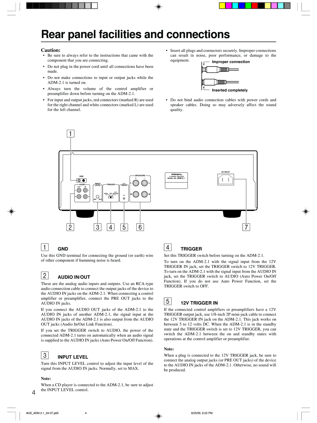
GND | SPEAKERS |
|
| |
2 CHANNEL AMPLIFIER | ||||
| ||||
AUDIO | INPUT | TRIGGER | 12 V | L | L | |
LEVEL | TRIGGER |
|
| |||
OUT | IN |
|
|
| ||
|
|
|
|
| ||
LL
AUDIO OFF | 12 V |
|
|
TRIGGER | R | R | |
|
| ||
|
| IN |
|
RR
MIN MAX
GND
Use this GND terminal for connecting the ground (or earth) wire of other component if humming noise is heard.
AUDIO IN/OUT
These are the analog audio inputs and outputs. Use an
If you connect the AUDIO OUT jacks of the
If you set the TRIGGER switch to AUDIO, the power of the connected
INPUT LEVEL
Turn this INPUT LEVEL control to adjust the input level of the signal from the AUDIO IN jacks. Normally, set to MAX.
Note:
When a CD player is connected to the
4 the INPUT LEVEL control.
TRIGGER
Set this TRIGGER switch before turning on the
To turn on the
12V TRIGGER IN
If the connected control amplifiers or preamplifiers have a 12V TRIGGER output jack, use
Note:
When a plug is connected to the 12V TRIGGER jack, be sure to connect the analog output jacks (or PRE OUT jacks) of the device to the AUDIO IN jacks of the
4 | 8/25/00, 6:22 PM |