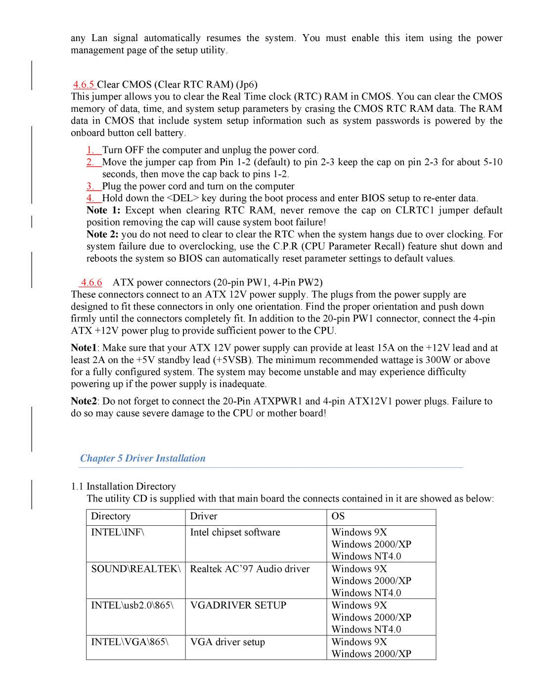
865 specifications
The Intel 865 chipset, introduced in early 2004, played a significant role in the evolution of computer architecture, particularly during the transition towards more advanced processing needs and increased graphical performance. This chipset was designed primarily for Intel Pentium 4 and Intel Celeron processors, making it compatible with a wide range of systems aimed at both mainstream and enthusiast users.One of the main features of the Intel 865 chipset is its support for dual-channel DDR memory, which effectively doubled the available memory bandwidth compared to single-channel configurations. This enhancement was crucial for improving system performance, particularly in tasks demanding high memory throughput, such as gaming and content creation. The chipset supported DDR400 memory, allowing users to enjoy faster data transfer rates and improved multitasking capabilities.
Another important technological advancement within the Intel 865 chipset is its integrated AGP 8X slot. This provided extensive support for high-end graphics cards, ensuring users had access to the necessary bandwidth for demanding graphical applications and games. The chipset's architecture was designed to maximize performance by reducing latency and improving overall system responsiveness.
The Intel 865 also included Intel’s Enhanced Memory 2 Technology, which offered greater flexibility in memory options. Users could utilize memory modules with different configurations while still benefiting from optimal performance levels. This feature was particularly advantageous for users who sought to upgrade their systems without replacing all existing memory components.
In terms of connectivity, the Intel 865 showcased support for the Intel Fast Ethernet controller, providing efficient networking capabilities for home and office environments. Additionally, it featured support for Serial ATA (SATA), an advancement over the older Parallel ATA technology, allowing for faster data transfer rates, improved storage options, and better overall system performance.
The chipset also offered Intel’s Advanced Configuration and Power Interface (ACPI), streamlining power management by allowing the operating system to control the amount of power that each component used. This feature resulted in better energy efficiency and longer battery life for laptops and mobile devices.
In summary, the Intel 865 chipset marked a pivotal point for desktop and mobile computing, providing significant improvements in memory management, graphics performance, and power efficiency. Its comprehensive feature set and compatibility with a variety of systems have left a lasting legacy in the evolution of computing technology.

