Manuals
/
Intel
/
Computer Equipment
/
Computer Hardware
Intel
user manual
Model Number:AW-A795, User’s Manual, Control Board, Version, Copyright
Models:
AW-A795
1
1
54
54
Download
54 pages
37.63 Kb
1
2
3
4
5
6
7
8
Specs
Install
Password
Pnp/Pci Configuration
Save & Exit Setup
Connector
BIOS Setup
Setting
Load Fail-Safe Defaults
How to
Page 1
Image 1
Page 1
Page 2
Page 1
Image 1
Page 1
Page 2
Contents
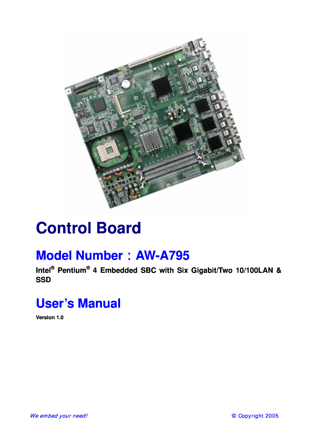
User’s Manual
Model Number:AW-A795
Intel Pentium 4 Embedded SBC with Six Gigabit/Two 10/100LAN SSD
Control Board
Trademarks
Copyright 2005. All Rights Reserved Manual Edition 1.0, January
Limitation of Liability
Specification
Table of Contents
1.5 Board Dimension
Chapter 2. Connectors Location and Configuration
Chapter 3. BIOS Setup
JP3Speak Buzzer Enable
3.1 Quick Setup
3.2 Entering the CMOS Setup Program
1.1Introduction
Chapter 1. General Information
CPU BIOS Chipset I/O Chipset Memory Enhanced IDE Serial port
1.2Specification
Parallel port KB/Mouse connector USB connectors PCI Slot
Watchdog Timer System Monitoring Digital I/O
1.3AW-A795 Package
Precautions
1.4 Board Layout 1.5 Board Dimension
Chapter 2. Connectors/Switch Location and Configuration
Define
Connector
USB0 Connector
LAN 10/100 Connector LAN 10/100 Connector
2.2. Installing Processors
2.2.1 Installing CPU
3 Now you can take out the CPU from socket
2.2.2 Remove CPU 1 First, please push the tappet to unlock location
1 Pentium M CPU Socket 2 PIII CPU - uFCPGA Package
2.2.3 How to recognize CPU
3 Pentium 4 CPU Socket 2.3 Installing Memory To insert a DIMM Memory
To Insert a DIMM Memory Please align the module with the socket key and press down until the levers at each end of the socket snap close up
Ver 1.0. Jan
CN1 USB0 Connector
2.4 Connector and Jumper Settings
CN4/5/6/7/8/9Gigabit LAN connector
CN2/3 LAN 10/100 Connector
Pin Define
CN11/20/24/28/29/30/31FAN Connector CN12Power LED Pin Header
CN13USB1 Pin Header Pin Define
CN14 COM2 Box Header
CN17Mini PCI
CN25IDE 2mm 44Pin 90 degree
CN18 GPIO Pin Header
CN26IDE2.54mm 40 Pin Connector
JP1PS/On/Always On Select
Setting
JP6Clear CMOS
JP2/4/5PCI-X Slot Frequency Select
JP3Speak Buzzer Enable
Frequency
Chapter 3. BIOS Setup
Enter the CMOS Setup program’s main menu as follows
3.2Entering the CMOS Setup Program
ADVANCED BIOS FEATURES
STANDARD CMOS FEATURES
ADVANCED CHIPSET FEATURES
POWER MANAGEMENT SETUP
LOAD OPTIMIZED DEFAULTS
LOAD FAIL-SAFE DEFAULT
SET SUPERVISORS & USER PASSWORD
SAVE & EXIT SETUP
Use the Advanced BIOS Features Setup option as follows
Advanced BIOS Features Setup
Option
Description
Virus Warning
Use the Advanced Chipset Features Setup option as follows
Advanced Chipset Features Setup
to this memory area, a system error may result
Use the Integrated Peripherals Setup option as follows
Use the Power Management Setup option as follows
Power Management
Use the PNP/PCI Configuration Setup option as follows
Option
Load Fail-Safe Defaults
PC Health Status Configuration Setup
Load Optimized Defaults
Supervisor/User Password
Exit Without Saving
Save and Exit Setup
Use this function to exit Setup without saving the CMOS value
Chapter 4. Driver Utility
The system driver installation procedure must be performed first
4.1.1. Intel 82546EB Ethernet 1 Choose Ethernet Controller
2 Choose Driver 3 Click Next
4 Click Next 5Click Next
6 Click Next 7 Click Finish
2 . Select the Drivers/system file to click the Setup icon
4.1.2 Intel 82551 Ethernet Installation
Please install Ethernet drivers as follows
1. Insert the AW-A795 CD-ROM driver into the CD-ROM Drive
3 Click Next 4 Click Next
5 Click Next 6 Click Next
7 Click Finish
4.2.1 Install System Chipset Driver
1 Click Next 2 Click Yes 3 Click Next
4 Click Finish
Installation process is completed and allowed the system to reboot
Assignment
Appendix A System Resource Interrupt Controller
Channel
Memory below 1MB 1Mb ~ 640KB
Memory Map
Address Range
Type
User’s Manual
Cable Description
Appendix B Standard Cable List
AW-A795
Terminating
Top
Page
Image
Contents