Installing the AXXRSBBU6
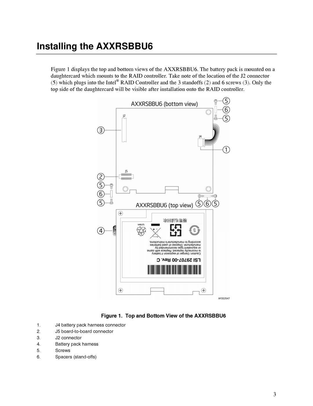
Figure 1 displays the top and bottom views of the AXXRSBBU6. The battery pack is mounted on a daughtercard which mounts to the RAID controller. Take note of the location of the J2 connector
(5)which plugs into the Intel® RAID Controller and the 3 standoffs (2) and 6 screws (3). Only the top side of the daughtercard will be visible after installation onto the RAID controller.
Figure 1. Top and Bottom View of the AXXRSBBU6
1.J4 battery pack harness connector
2.J5
3.J2 connector
4.Battery pack harness
5.Screws
6.Spacers
3