Manuals
/
Intel
/
Computer Equipment
/
Network Card
Intel
CV702A, CV700A
manual
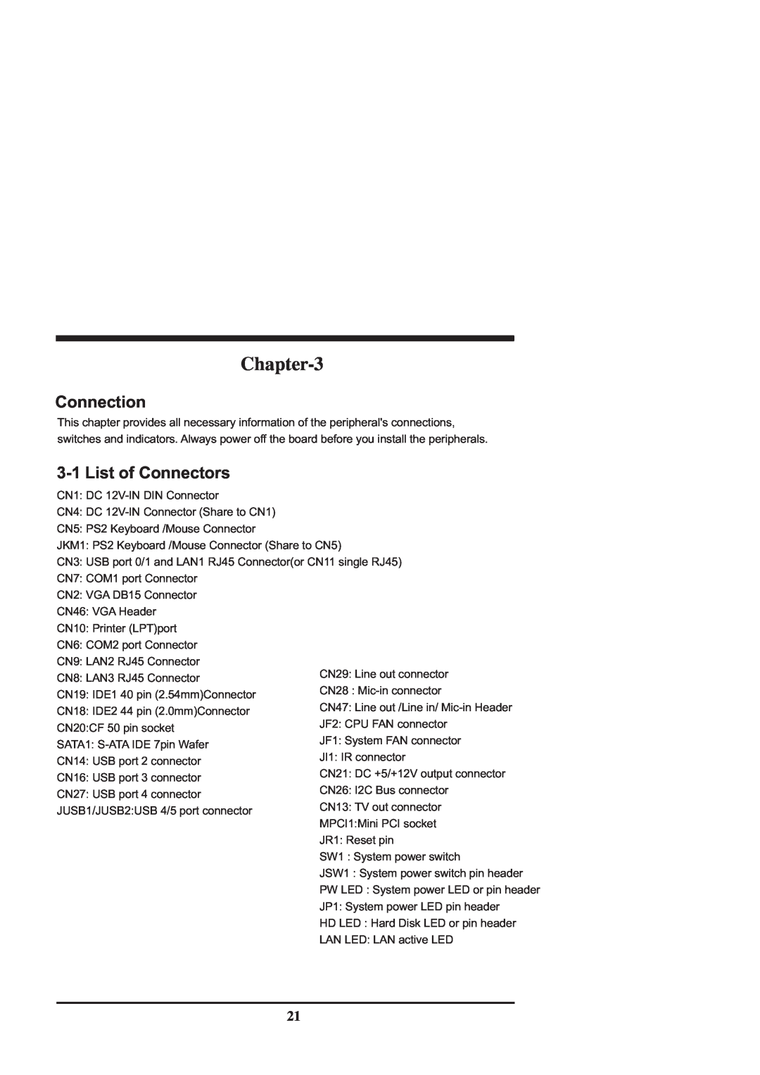
Connection, 3-1List of Connectors
Models:
CV702A, CV700A
CV700A
1
25
63
63
Download
63 pages
43.33 Kb
22
23
24
25
26
27
28
29
Specs
Install
2-5Diagram
Password
Dimension
Valid Memory Configurations
4-1Enter Setup
3-1List of Connectors
Advanced BIOS Features
Battery
Page 25
Image 25
Page 24
Page 26
Page 25
Image 25
Page 24
Page 26
Contents
CV700A / CV702A
NO.CV700A / CV702A Release date: OCT.26.2006
400MHz FSB / VGA / LAN / Sound
400MHz FSB . All-in-one Sound . 3 LAN
CHAPTER
Contents
CHAPTER
2006
General lnformation
Chapter-1
1-1Major Feature
6.I/O Chipset: VIA VT1211IO
1-2Specification
1-3Hardware Notice Guide
Insert 1
Photo
2 3 Unplug 1 2 3
1-3-1Installing the Mini PCI card
Notices
1-3-1.1Removing the Mini PCI card
12 56
1-4Packing List
3 7 8
Hardware Installation
2-1Unpacking Precaution
Chapter-2
2-2Unpacking checkup
200x150mm
2-3 Dimension
CN700 VT8237R-Plus
2-4Layout
LAN3
CN20
2-5Diagram
Back Panel CV700A
2-5-1Bottom Side Diagram
Back Panel CV702A
Valid Memory Configurations
2-6Install Memory
Figure
Total Memory
JB1: CMOS DATA SET
2-7List of Jumpers
JCF1: CF card mast and slave select
JCF2: CF card Voltage select
2-9CMOS Data Set
2-8Jumper Setting Description
Figure
1.Troubleshooting 2.Forget password
2-10JCF2 CF Card Power Voltage select
3.You fail over-clockingsystem
We use
JCF1
2-11JCF1 CF Card Master and Slave selection
Master* Slave
3 2 1
Chapter-3
3-1List of Connectors
Connection
3-3IDE Connectors
3-2FAN Connector
44 pins2.0mm-CN18IDE2
3-4Compact - Flash Memory Socket
CN10: Printer LPTPort ---CN10 D-SUB25 PIN
3-5Parallel Port Connector
CN7 COM1 Connector D-SUB 9-Pin
3-6Serial Port Connector
CN6: COM2 Connector D-SUB 9-pin
CN5: PS2 Keyboard down side Din 6 pin jack
3-7Keyboard and Mouse Connector
CN5: PS2 Mouse up side Din 6 pin jack
3-8USB Port/ Header
1.25mm Wafer connector
CN14 / CN16 : USB port 2/3 pin
JUSB1/JUSB2 USB 4/5 port
3-10VGA Connector
3-9IR Connector
JI1: IR connector ---5pin1.25mm Wafer connector
CN2: VGA DB15 Connector Up side D SUB 15PIN
CN8: LAN3 RJ45 Connector
CN9: LAN2 RJ45 Connector
3-11LAN Port
LAN Led
CN29 Phone Jack
3-12Audio Port Connector
Line-OUT
CN28 Phone Jack
3-13DC 12V IN and DC out
3-14DC +5/+12V output connector
3-15Serial ATA
3-16I2 C Bus Connector
SATA1: S-ATAIDE 7pin Wafer
JR1: System Reset key 2.0mm pin header
3-17 TV-OUTConnector
Power switch: PW-ON---SW1 JSW1: Power on switch
Power LED: PW-LED /JP1
4-1Enter Setup
Introduction of BIOS
Chapter
4-2Getting Help
Status Page Setup Menu/ Option Page Setup Menu
4-3The Main Menu
Main Menu
Advanced BIOS Features
Standard CMOS Features
Advanced Chipset Features
Power Management Setup
Load Standard Defaults
4-4Standard CMOS Features
Set Supervisor/User Password
Save & Exit Setup
Virus Warning
4-5Advanced BIOS Features
4-6-1DRAM Clock/Drive Control
4-6Advanced Chipset Features
Phoenix- AwardBIOS CMOS Setup Utility
Advanced Chipset Features
4-7Integrated Peripherals
4-6-2AGP & P2P Bridge Control
AGP & P2P Bridge Control
Integrated Peripherals
VIA-3058AC97 AUDIO
4-7-1VIA OnChip IDE Device
Phoenix - AwardBIOS CMOS Setup Utility
4-7-2VIA OnChip PCI Device
4-7-3Super IO Device
4-8Power Management Setup
IRQ / Event Activity Detect
4-8-1.1IRQs Activity Monitoring
4-8-1IRQ / Event Activity Detect
IRQs Activity Monitoring
Resource Controlled By
4-9PnP / PCI Configuration Setup
IRQ Resources
PCI/VGA Palette Snoop
Show PC Health in Post
4-10PC Health Status
Vcore/3.3V/+5V/+12V
Load Standard Defaults
4-12Load Fail-Safe/OptimizedDefaults
Load Optimized Defaults
4-11Frequency/Voltage Control
ENTER PASSWORD
4-13Set Supervisor/ User Password
PASSWORD DISABLED
SYSTEM INSTALL Supports WINDOWS
DRIVER INSTALLATION
From MAGIC INSTALL MENU you may make 3 selections
98/98SE/ME/2000/XP
Auto install driver Menu
1.Click VIA 4 IN 1 when System Install
5-1VIA 4 IN 1 Install VIA IDE/AGP/ INF Driver
2.Click NEXT when VIA Service Pack
INSTALLED UNDER WIN98 ONLY
X:\driver\VIA\CN700\4IN1\setup.exe
NOTE: SYSTEM INSTALL will auto detect file path
7.Click Finish to restart computer
1.Click VGA when System Install MENU appears
5-2VGA INSTALL CN700 VGA Driver
Click NEXT
4. Click FINISH to Restart Computer
1.Click SOUND when System Install
5-3SOUND Install VIA Audio Codec Driver for VIA
2. Click NEXT install VIA AC97 Audio Driver
3.Click NEXT install VIA AC97 Audio Driver
1.Click USB2.0 when System Install MENU appears
5-4USB2.0 install VIA USB2.0 Installing driver
2. Click NEXT install USB2.0 Driver
3. Click NEXT install VIA USB2.0 Driver
5-6HOW TO UPDATE BIOS
5-5HOW TO DISABLE ON-BOARDSOUND
Appendix B: Resolution list
Appendix A: Power Consumption Test
Condition
Test Result for reference
2. Battery
1. CF card & 2.5” HDD first boot issue
3. Fanless solution with HDD
2. Battery
1. CF card & 2.5” HDD first boot issue
Battery on board is consumables. Lex doesn’t guarantee the life time of it
3. Fanless solution with HDD
Top
Page
Image
Contents