Installing and Replacing Desktop Board Components
Connecting Internal Headers
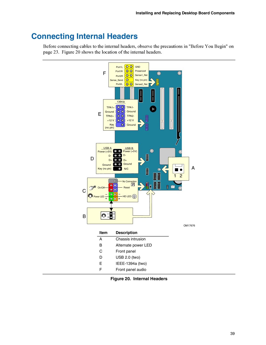
Before connecting cables to the internal headers, observe the precautions in "Before You Begin" on page 23. Figure 20 shows the location of the internal headers.
F
Port1L | 1 | 2 | GND |
Port1R | 3 | 4 | Presence# |
Port2R | 5 | 6 | Sense1_Ret |
| |||
Sense_Send | 7 |
| Key (no pin) |
Port2L | 9 | 10 | Sense2_Ret |
E
| 1394 a |
| |
TPA1+ | 1 | 2 | TPA1- |
Ground | 3 | 4 | Ground |
TPA2+ | 5 | 6 | TPA2- |
+12 V | 7 | 8 | +12 V |
Key |
| 10 | Ground |
(no pin) |
|
|
|
| USB A |
|
| USB B |
| Power (+5V) | 1 | 2 | Power (+5V) |
D | D- | 3 | 4 | D- |
D+ | 5 | 6 | D+ | |
| Ground | 7 | 8 | Ground |
| Key (no pin) |
| 10 | N/C |
|
| 9 |
| No Connection |
| 8 | 7 |
| Reset |
C | On/Off | 5 |
| |
6 |
|
| ||
4 | 3 |
|
| |
|
| HD LED | ||
Power LED | 1 |
| ||
| 2 |
|
| |
B | 3 |
1 |
Item Description
AChassis intrusion
BAlternate power LED
CFront panel
DUSB 2.0 (two)
E
FFront panel audio
A
1 2
OM17676
Figure 20. Internal Headers
39