Intel Desktop Board DG965RY Product Guide
Connecting to the USB 2.0 Header
Before connecting to the USB 2.0 header, observe the precautions in "Before You Begin" on page 25. See Figure 22, G on page 42 for the location of the black USB 2.0 header. Table 11 shows the pin assignments for the USB 2.0 header.
Table 11. USB 2.0 Header Signal Names
| USB Port A |
Pin | Signal Name |
|
|
1 | Power (+5 V) |
3 | D- |
|
|
5 | D+ |
7Ground
9Key
| USB Port B |
Pin | Signal Name |
|
|
2 | Power (+5 V) |
4 | D- |
|
|
6 | D+ |
8 | Ground |
10 | No Connection |
Note: USB ports may be assigned as needed.
Connecting to the Flexible Audio System
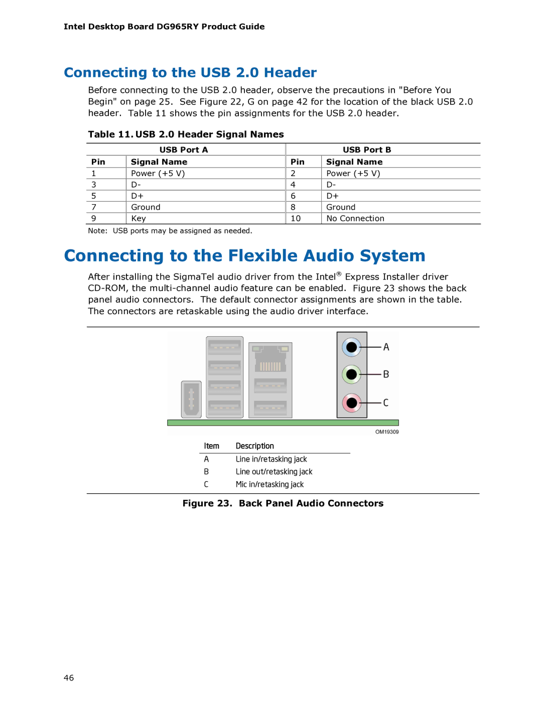
After installing the SigmaTel audio driver from the Intel® Express Installer driver
Item Description
ALine in/retasking jack
BLine out/retasking jack
CMic in/retasking jack
Figure 23. Back Panel Audio Connectors
46