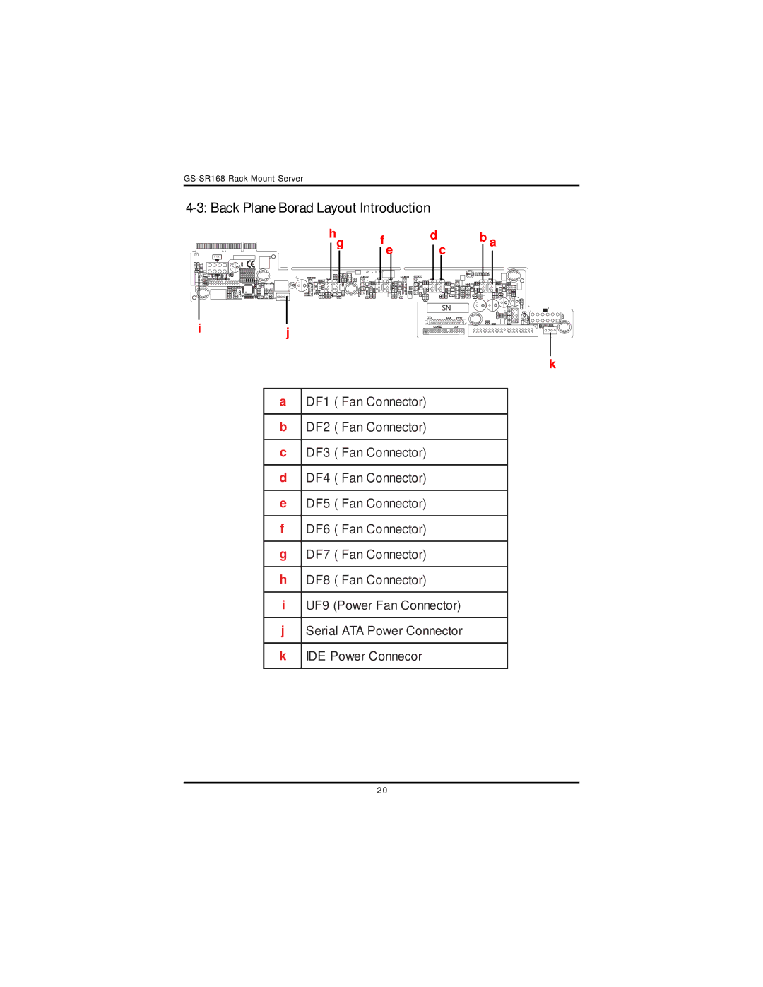
4-3: Back Plane Borad Layout Introduction
0
ATX2
1
i
hg f e
ASSEM:
j
d
c
SN
251
262
b a
4 5
1 8
| 12 |
| 7 |
+ | 1 |
| 6 |
k
a | DF1 ( Fan Connector) |
|
|
b | DF2 ( Fan Connector) |
|
|
c | DF3 ( Fan Connector) |
|
|
d | DF4 ( Fan Connector) |
|
|
e | DF5 ( Fan Connector) |
|
|
f | DF6 ( Fan Connector) |
|
|
g | DF7 ( Fan Connector) |
|
|
h | DF8 ( Fan Connector) |
|
|
i | UF9 (Power Fan Connector) |
|
|
j | Serial ATA Power Connector |
|
|
k | IDE Power Connecor |
|
|
2 0
