DG35EC, Intel Desktop Board specifications
The Intel Desktop Board DG35EC is a versatile and reliable motherboard designed for the Intel Core 2 Processor family. Launched in the mid-2000s, it became known for its solid performance and robust feature set aimed at both general computing and home entertainment needs.One of the standout features of the DG35EC is its support for the Intel Core 2 Duo and Core 2 Quad processors. With LGA775 socket compatibility, it allows users to take advantage of the multi-core architecture for improved multitasking capabilities and overall performance. The board supports a maximum memory capacity of 8GB using DDR2 RAM, offering dual-channel architecture for enhanced memory bandwidth, which is crucial for tasks that require significant data processing.
The DG35EC is built with Intel's G35 Express chipset, which integrates several key technologies to enhance user experience. This chipset combines graphics and memory functionality, allowing for seamless multimedia playback and enabling support for DirectX 10. The integrated Intel Graphics Media Accelerator X3000 delivers decent graphics performance for day-to-day applications and light gaming, which was impressive at the time of its release.
This desktop board also boasts a suite of connectivity options. It features six SATA 3Gb/s ports for fast data transfer with compatible hard drives and SSDs, enhancing system responsiveness. Additionally, it includes a wide array of USB 2.0 ports, enabling users to connect multiple peripherals, such as external storage devices, printers, and keyboards without the need for expansion cards.
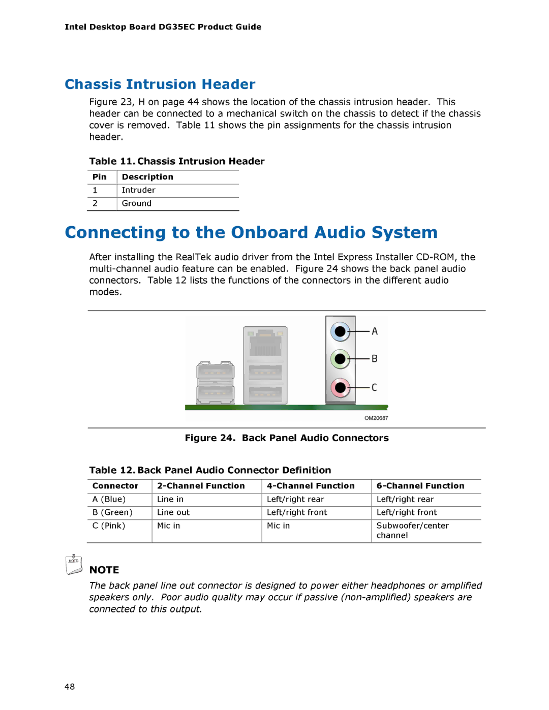
For audio capabilities, the DG35EC is equipped with Intel High Definition Audio, providing immersive sound quality for multimedia applications and improved audio fidelity for high-definition content. This feature was particularly appealing for users who enjoyed media consumption on their desktop systems.
The board is also designed with various expansion slots, including PCI Express x16 for graphics cards, and several PCI slots for legacy devices, thus ensuring compatibility with a wide range of hardware. The compact ATX form factor makes it suitable for a variety of cases while providing sufficient room for expansion.
Overall, Intel's DG35EC Desktop Board stands out for its reliable performance and feature set tailored for everyday computing and multimedia applications, making it a solid choice for users looking to build a functional and efficient desktop system.

