USER’S MANUAL
Intel Atom 945GSE Mini-ITX Motherboard
Version
MI810
Acknowledgments
Introduction
Installations
BIOS Setup
Drivers Installation
This page is intentionally left blank
INTRODUCTION
Introduction
Product Description
1 CD containing chipset drivers and flash memory utility
Checklist
Your MI810 package should include the items listed below
The MI810 Intel Atom Mini-ITX motherboard This User’s Manual
MI810 Specifications
Board Dimensions
MI810 User’s Manual
Connectors on MI810
Installations
INSTALLATIONS
Setting the Jumpers
DDR2 Module Lock
Installing the Memory
Installing and Removing Memory Modules
Lock
Setting the Jumpers
Page
Jumper Locations on MI810
Jumpers on MI810
JP2 ATX/AT Mode Select
JP1 LCD Panel Power Selection
LCD Panel Power
Signal Name
Setting
JP6 COM4 RS232 +5V / +12V Power Setting
JP7 COM3 RS232 +5V / +12V Power Setting
JP8 Clear CMOS Setting
Connectors on MI810
Connector Locations on MI810
INSTALLATIONS
CN1 DC Jack DC in, 12V or
FAN1 CPU Fan Power Connector
FAN2 System Fan Power Connector
CN2 PS/2 Keyboard and PS/2 Mouse Connectors
CN5 10/100 RJ-45 and USB1/2 Ports CN6 GbE RJ-45 and USB3/4 Ports
CN3 VGA and DVI Connectors
CN7 Audio Connector
CN4 USB5/6 Ports
PCI1 PCI Slot supports 2 Master PCIE1 PCIE x1 Slot IDE1 IDE Connector
CN8, CN9 Serial ATA Connectors
CN10 Mini PCI- Ex1 Connector bottom side
CN11 Compact Flash Connector bottom side
J5 Power LED Connector
J1, J4 LCD Backlight Connector
J2 HDD Power Connector Output Max. 2A
J3 ATX12V Connector
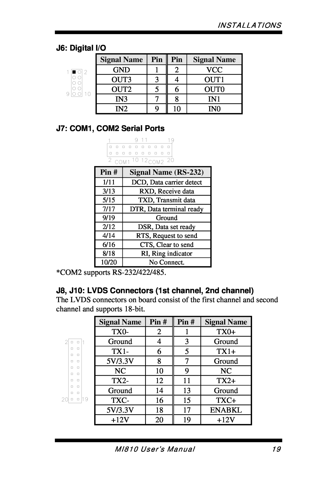
J7 COM1, COM2 Serial Ports
Signal Name RS-232
J8, J10 LVDS Connectors 1st channel, 2nd channel
J6 Digital I/O
J13 USB7/8 Port Pin Header
J9 System Function Connector
J12 Wake On LAN Connector
J11 COM3, COM4 Serial Ports
J14 Audio Front Header
Signal Name Pin #
J17 Smart Battery Connector
J18 SPDIF Out Connector
This page is intentionally left blank
BIOS Setup
Press DEL to Enter Setup
BIOS Introduction
BIOS Setup
Standard CMOS Features
Date
Standard CMOS Setup
CYLS
Time
IDE Channel Master/Slave
Capacity
Halt On
Virus Warning
Advanced BIOS Features
CPU Feature
Hard Disk Boot Priority
Boot Up Floppy Seek
Quick Power On Self Test
First/Second/Third Boot Device
Boot Other Device
MPS Version Control for OS
Typematic Delay Msec
Security Option
APIC Mode
DRAM RAS# to CAS# Delay
Advanced Chipset Features
DRAM Timing Selectable
CAS Latency Time
Precharge Delay tRAS
System BIOS Cacheable
Video BIOS Cacheable
On-Chip VGA Setting
The default setting is Auto. The options available include On and Off
Panel Scaling
Panel Number
SuperIO Device
Integrated Peripherals
OnChip IDE Device
Onboard Device
OnChip Primary/Secondary PCI IDE
IDE DMA Transfer Access
On-chip Primary PCI IDE Enabled
IDE HDD Block Mode
Hot Key Power ON
On-Chip Serial ATA Setting
Power ON Function
KB Power ON Password
3F8/IRQ4
Onboard Serial Port
PWRON After PWR-Fail
Serial Port
ACPI Function
Power Management Setup
RUN VGABIOS if S3 Resume
Power Management
Video Off In Suspend
HDD Power Down
Power On by Ring
Video Off Method
Reload Global Timer Events
Resume by Alarm
Resources Controlled by
PNP/PCI Configurations
Reset Configuration Data
Init Display First
Smart Fan Temperature
PC Health Status
CPU Warning Temperature
Temperatures/Voltages
CPU Host / SRC PCI Clock
Frequency/Voltage Control
Auto Detect PCI Clk
Spread Spectrum Modulated
Save & Exit Setup
Load Fail-Safe Defaults
Load Optimized Defaults
Set Supervisor Password
Save & Exit Setup
IMPORTANT NOTE
Drivers Installation
2. Click IntelR Chipset Software Installation Utility
Intel Chipset Software Installation Utility
3. When the Welcome screen to the IntelR Chipset Software Installation Utility appears, click Next to continue
VGA Drivers Installation
6. Setup is now complete. Click Finish to restart the computer
2. Click Realtek Audio Driver and then Realtek High Definition Codec
Realtek High Definition Audio Driver Installation
Audio Driver
2. In the next screen, click Install Drivers and Software
LAN Drivers Installation
7. When the InstallShield Wizard has been completed, click Finish
Device Description
Appendix
A. I/O Port Address Map
Address
Level
B. Interrupt Request Lines IRQ
SAMPLE CODE
C. Watchdog Timer Configuration
switch to logic device
=========================================================================== #include W627EHF.H
0xAA