SIU520 SS7 specifications
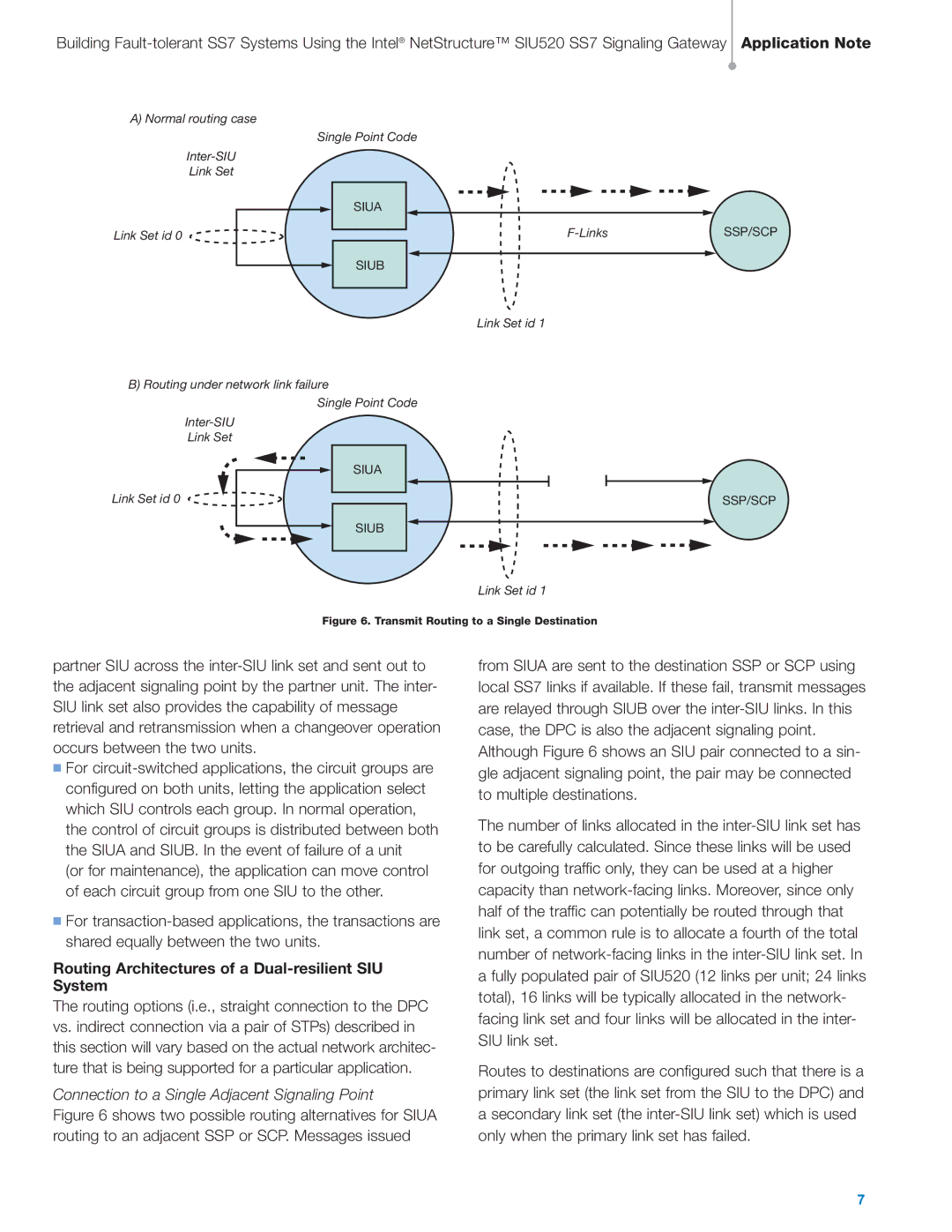
The Intel SIU520 SS7 is a significant advancement in the realm of telecommunications, specifically designed for seamless signaling in a wide array of telecommunication infrastructures. As a part of Intel's pioneering suite of products, the SIU520 plays a critical role in managing signaling for telephony systems that require efficient handling of SS7 protocols.One of the main features of the SIU520 is its support for the SS7 signaling protocol, which is pivotal for the establishment and management of telephone calls over traditional circuit-switched networks. With its robust design, the SIU520 ensures reliability in signaling, contributing to the reduction of call set-up times and the minimization of errors, thus enhancing the overall quality of communication services.
The SIU520 incorporates advanced technologies such as high-speed data processing capabilities, allowing it to handle multiple signaling messages concurrently. This is particularly important in environments with high call volumes, where efficient processing can significantly affect the performance of telecommunication services. Furthermore, the architecture of the SIU520 is designed for scalability, enabling easy integration into existing infrastructures while accommodating future expansions as demand increases.
Another characteristic that sets the SIU520 apart is its support for various signaling types beyond standard SS7, including ISDN and SIP. This makes it a versatile tool for service providers aiming to offer diverse services, such as voice, video, and data communications. The SIU520 is also designed with a focus on interoperability, which ensures that it can effectively communicate with equipment from different manufacturers, thus providing flexibility in deployment.
In terms of security features, the SIU520 is architected to withstand common threats in the communication landscape. It employs encryption and authentication protocols to safeguard signaling traffic, ensuring that sensitive information remains protected during transmission.
In summary, the Intel SIU520 SS7 represents a robust and flexible signaling solution crucial for modern telecommunications. With its support for multiple protocols, high processing speeds, scalability, and secure communication capabilities, it stands as a testament to Intel's commitment to advancing telecommunication technologies and enhancing the efficiency and reliability of communication networks worldwide.

